Plasma body cleaning device

A cleaning device and plasma technology, which is applied in the direction of cleaning methods and appliances, chemical instruments and methods, etc., can solve the problems of low plasma density, narrow working pressure range, and difficult technology development, so as to avoid electrode pollution and facilitate Control and protection, better cleaning effect

Inactive Publication Date: 2010-09-22
浙江尧瑶科技有限公司
View PDF8 Cites 8 Cited by
  • Summary
  • Abstract
  • Description
  • Claims
  • Application Information

AI Technical Summary

Problems solved by technology

However, since plasma cleaning technology involves the research of plasma physics, plasma chemistry and material gas-solid phase interface characteristics, it needs to integrate various technologies such as chemical industry, materials and electronic machinery, so it is difficult to develop the technology
On the other hand, the corresponding existing plasma cleaning equi

Method used


Image

  • Plasma body cleaning device
  • Plasma body cleaning device
  • Plasma body cleaning device

Examples


Embodiment 1

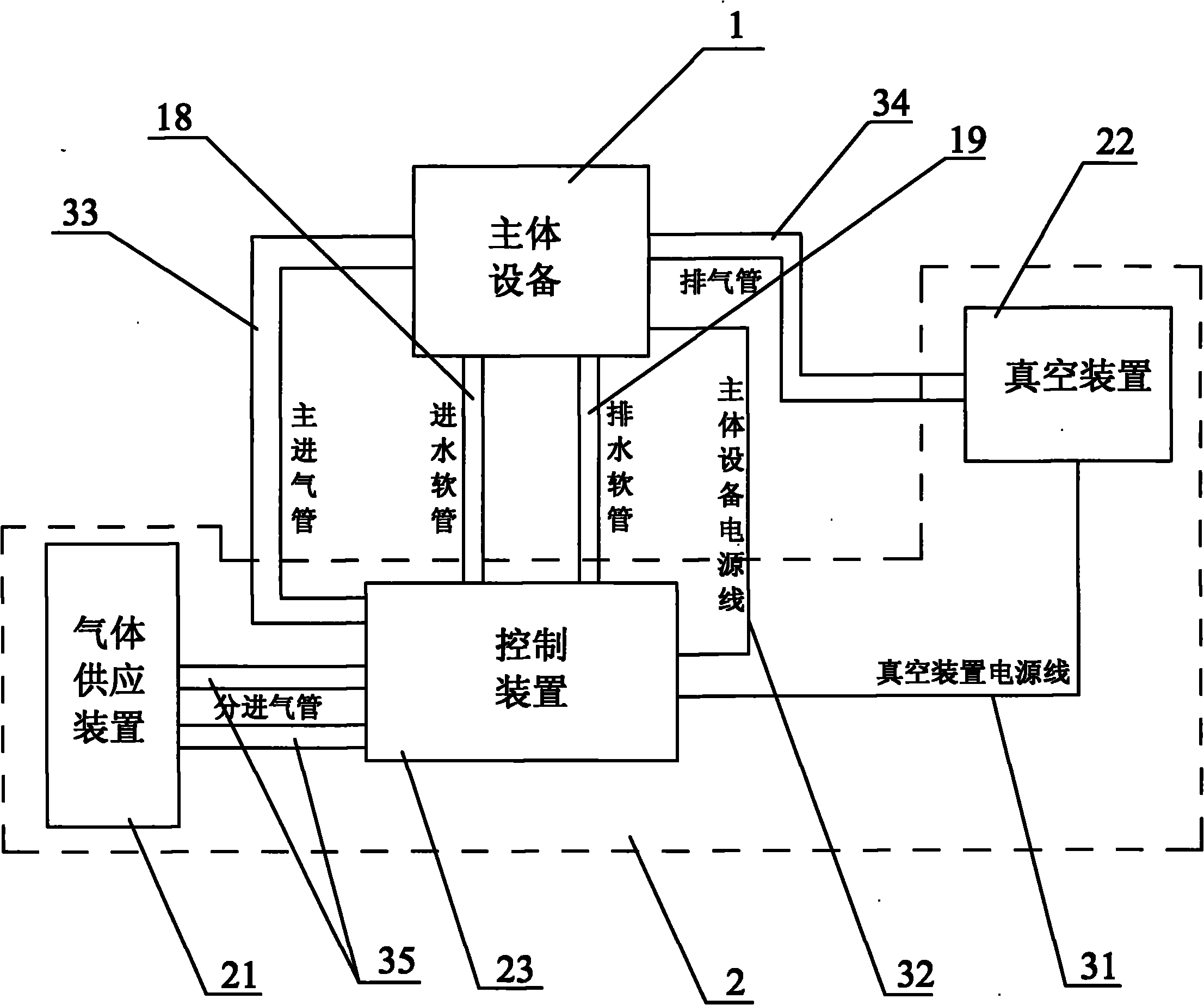
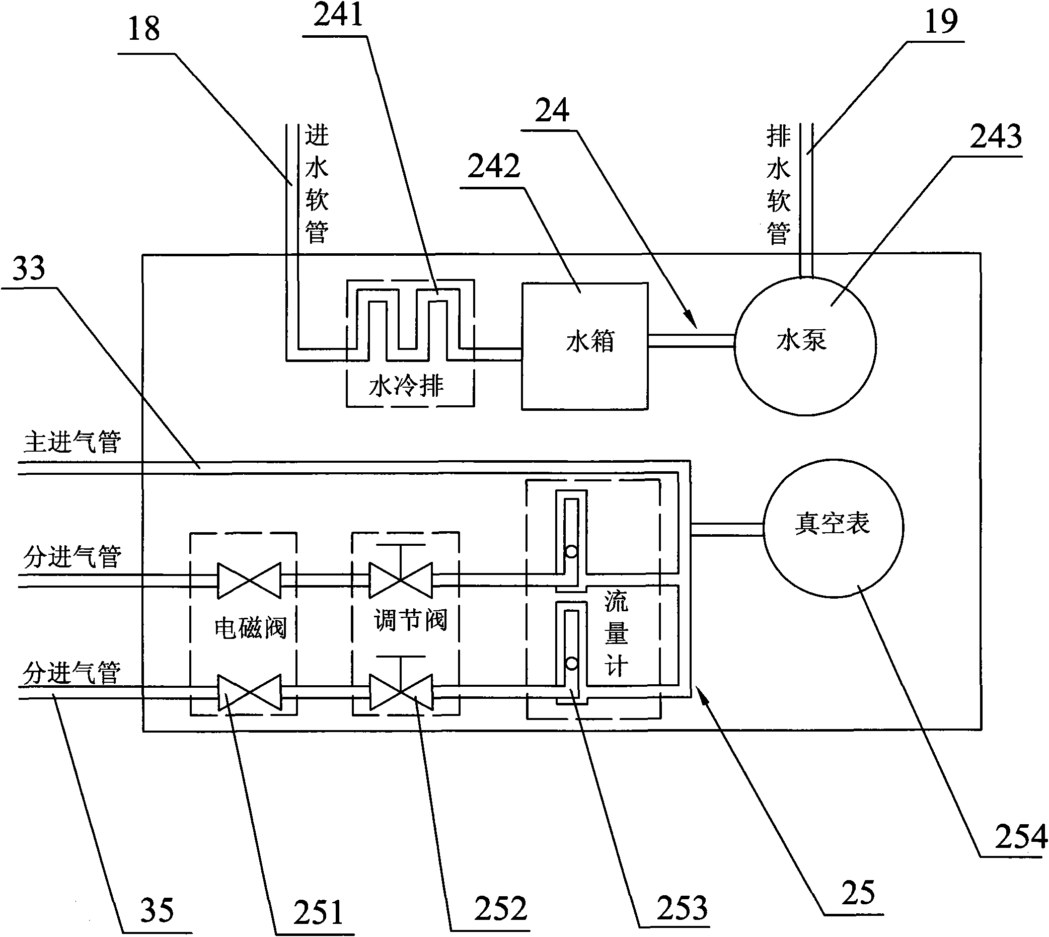
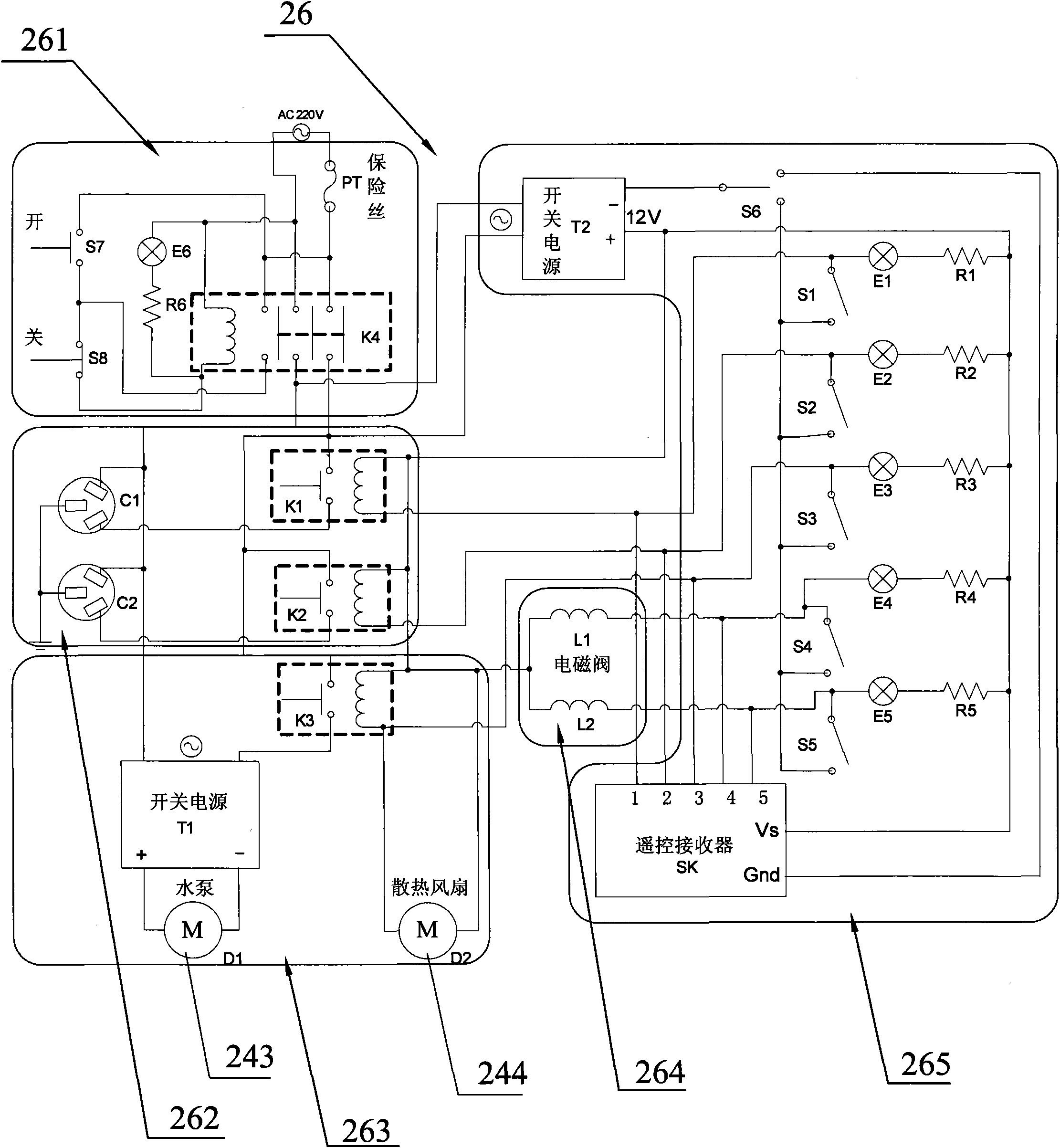
[0029] Such as Figure 1 to Figure 5 As shown, a plasma cleaning device includes a main device 1 and a peripheral device 2. The peripheral device 2 is mainly composed of a gas supply device 21, a vacuum device 22, and a control device 23. The control device 23 includes a water circuit unit 24 and a gas circuit unit 25. And the circuit unit 26, the main device 1 is mainly composed of a microwave system 11 and a reaction device 12. The microwave system 11 includes a microwave chamber 13, a microwave source 14 arranged in the microwave chamber 13, and a microwave control circuit electrically connected to the microwave source 14 (Figure (Not shown), the reaction device 12 includes a quartz cover 15 arranged in the microwave chamber 13, a reaction chamber base 16 arranged in the microwave chamber 13 and arranged below the quartz cover 15, and surrounded by the quartz cover 15 and the reaction chamber base 16. The microwave control circuit is connected to the circuit unit 26 through t...

Embodiment 2

[0039] Such as Figure 1 to Figure 3 and Image 6 As shown, the structure of this embodiment is basically the same as that of the first embodiment, except that the reaction chamber base 16 in this embodiment is a turntable reaction chamber base, such as Image 6 As shown, the reaction chamber base 16 is provided with a motor placement groove 51 that penetrates the bottom of the microwave chamber cavity 131, the motor placement groove 51 is in communication with the reaction chamber 17, and the motor placement groove 51 is provided with a motor 52. When placing the motor 52, the motor shaft 53 of the motor 52 needs to be vertically upward. The bottom of the motor placement groove 51 is provided with a lead through hole 54 for leading out the power line of the motor 52, and the power line of the motor 52 passes through the lead The through hole 54 is connected to the external motor power supply. The open end of the motor placement groove 51 is provided with a metal baffle 55 for i...


PUM


Abstract

The invention discloses a plasma body cleaning device, which mainly consists of a microwave system and a reaction device, wherein the microwave system comprises a microwave chamber, a microwave source and a microwave control circuit, the microwave source can be regulated and controlled through the microwave control circuit, and the regulation and the control on the density of the plasma body can be realized. The cleaning device effectively avoids the electrode pollution by adopting a microwave excitation mode, and simultaneously enlarges the pressure intensity work range. Because the microwave technology is mature, the microwave leakage can be easily controlled and protected, the cleaning device has good safety performance. The work pressure intensity can be controlled through regulating and controlling the flow speed of the cleaning reaction gas and the gas pumping speed of a vacuum device, the power of the microwave source can be controlled through the microwave control circuit, and the bombarding force on the surface of cleaning samples by the plasma body and the concentration of the plasma body can be effectively regulated. Thereby, the cleaning and the surface modification in different modes can be carried out according to the cleaning samples in different material types.

Description

Technical field [0001] The invention relates to a cleaning device, in particular to a plasma cleaning device. Background technique [0002] In the processing of optical devices and microelectronic components, surface cleaning technology has a very important position. At present, the widely used physical and chemical cleaning methods can be roughly divided into two types in terms of operation mode: wet cleaning and dry cleaning. Wet cleaning mainly relies on the effects of physical and chemical (solvents), such as the adsorption, soaking, dissolution and dispersion of chemical active agents, supplemented by physical methods such as ultrasonic, spray, rotation, boiling, steam and shaking to remove the surface of objects Stains. In the wet cleaning process, subsequent drying and wastewater treatment procedures are also required, and the labor protection and environmental pollution control costs are high. Dry cleaning mainly includes plasma cleaning technology, which mainly uses t...

Claims


Application Information

Patent Timeline
IPC IPC(8): B08B7/00
Inventor 周骏林豪仰明阳颜飞彪
Owner 浙江尧瑶科技有限公司
Why Eureka
Try Eureka