Translational rolling mechanism

A rewinding mechanism and translation technology, applied in the direction of winding strip, thin material handling, transportation and packaging, etc., can solve the problems of changing the tangent angle, difficult to stabilize the thrust F of the cylinder, and difficult to guarantee the quality of rewinding. The effect of keeping the coil pressure stable and the cylinder pressure easy to keep stable

Inactive Publication Date: 2010-09-22
汕头市双丰机械有限公司
View PDF8 Cites 19 Cited by
  • Summary
  • Abstract
  • Description
  • Claims
  • Application Information

AI Technical Summary

Problems solved by technology

[0004] The first type of winding mechanism such as figure 1 As shown, the characteristics of this mechanism are that the positions of the guide roller 12 and the winding shaft 2 are fixed during the winding process, and the center distance of the coil 11 from the guide roller 12 to the winding shaft 2 remains unchanged; the first mechanism is insufficient Yes: As the diameter of the finished roll increases, the transmission path between the guide roller 12 and the tangent point of the finished roll will evolve from the initial position AC to the final position BC, that is, the distance and tangent angle of the transmission path will change, resulting in The tension distribution of the coil is very uneven, and the winding quality is difficult to guarantee
Compared with the first three winding mechanisms, the winding quality of the above fourth winding mechanism has been improved, but there are still deficiencies, for example, the pressure between the finish

Method used


Image

  • Translational rolling mechanism
  • Translational rolling mechanism
  • Translational rolling mechanism

Examples


Embodiment 1

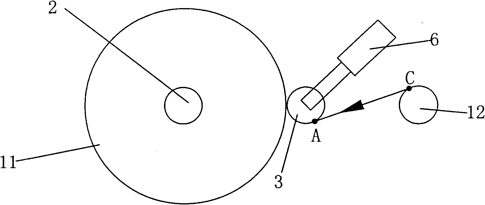
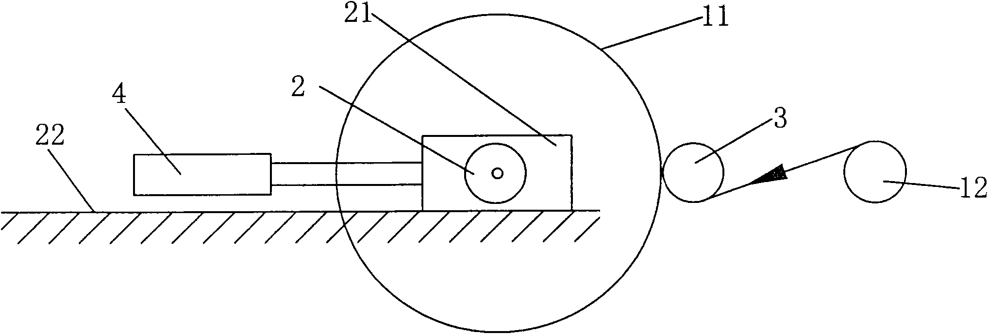
[0025] Figure 4 , Figure 5 , Figure 6 As shown, the rewinding mechanism of the translational center coiling includes a frame 1, a rewinding shaft 2, and a pressure roller 3. It is installed on the horizontal rail 22 in a forward and backward translational manner, and the two winding shaft supports 21 at the left and right ends are connected together through the middle connecting plate 23 . An oil cylinder 4 that can push the rewinding shaft support 21 to translate back and forth is also provided. The piston rod 41 of the oil cylinder is directly connected to the intermediate connecting plate 23, and viewed from the horizontal projection position, the axis of the piston rod 41 of the oil cylinder is located between the two rewinding shafts. The very center of the support 21. The winding shaft is also connected with a motor that drives its rotation.

[0026] Figure 4 , Figure 5 , Figure 6 As shown, the two ends of the touch roller 3 are installed on the touch roller...

Embodiment 2

[0037] In Embodiment 2, the structural form of the forward and backward movement of the touch roller bracket is linear translation back and forth, that is, the touch roller bracket can be mounted on the horizontal guide rail forward and backward (while the structural form of the forward and backward movement of the touch roller bracket in Embodiment 1 is front and rear swing). The touch roller support is connected with an air cylinder.

[0038] In addition, in the second embodiment, the sliding rod of the linear displacement sensor is directly connected with the touch roller bracket through the connecting piece. All the other are the same as the first embodiment.

[0039] In fact, since the cylinder piston ring, cylinder piston rod, and touch roller bracket are connected together, detecting the displacement of any one of them actually represents the detection of the displacement of the touch roller bracket. Therefore, the sliding rod of the linear displacement sensor can be ...


PUM


Abstract

The invention relates to a translational rolling mechanism. The translational rolling mechanism comprises a rack, a rolling shaft and a contact compression roller; a rolling shaft support is arranged on a horizontal rail in a mode of being capable of moving back and forth, and is provided with an oil cylinder capable of pushing the rolling shaft support to move back and forth; a contact compression roller support is arranged on the rack in a mode of being capable of moving back and forth, and is provided with an air cylinder which applies pushing force on the contact compression roller support, and the piston rod of the air cylinder is connected with the contact compression roller support; and the translational rolling mechanism also comprises a central control processor, a sensing air cylinder piston rod or a linear displacement sensor for the displacement of the contact compression roller support, wherein the linear displacement sensor is connected to the central control processor, the central control processor is connected with the drive circuit of the oil cylinder, and the central control processor controls the oil cylinder to operate according to the signal of the linear displacement sensor. The invention ensures that the pressure between a finished scroll and the contact compression roller is stable; the transmission path and clipped corner for a rolled material to entering into a finished roll remain unchanged all the time; and the rolling quality is ensured, thus the translational rolling mechanism is suitable for high-grade rolled material rolling, large-diameter rolled material rolling and high-speed rolling.

Description

technical field [0001] The invention belongs to a mechanism for winding coiled materials, in particular to a translational rolling mechanism. Background technique [0002] With the development of coiled products, people have higher and higher requirements for the quality of coiling. On the other hand, more and more coils hope to realize the large-diameter, high-speed, and large-width winding process, but the larger the diameter of the coil, the higher the speed, and the larger the width, the more difficult the winding quality control. [0003] In the prior art, there are the following four types of winding mechanisms for center winding: [0004] The first type of winding mechanism such as figure 1 As shown, the characteristics of this mechanism are that the positions of the guide roller 12 and the winding shaft 2 are fixed during the winding process, and the center distance of the coil 11 from the guide roller 12 to the winding shaft 2 remains unchanged; the first mechani...

Claims


Application Information

Patent Timeline
IPC IPC(8): B65H18/26
Inventor 李文川
Owner 汕头市双丰机械有限公司
Why Eureka
Try Eureka