Pressurized water injection device

A booster pump and four-way technology, applied in the field of equipment for oil field water injection, can solve the problems of inability to improve the permeability of the water injection layer, economic losses, frequent maintenance, etc., achieve significant economic and social benefits, improve permeability, and manage low difficulty effect

Active Publication Date: 2010-09-22
南通山口精工机电有限公司
View PDF6 Cites 10 Cited by
  • Summary
  • Abstract
  • Description
  • Claims
  • Application Information

AI Technical Summary

Problems solved by technology

[0002] Individual water injection wells require high-pressure water to be injected into the formation. Various oilfields have adopted a variety of booster equipment, such as surface plunger pumps and centrifugal pumps. These pumps are used to boost the pressure on the existing water injection pipe network and then inject them into injection water that requires high pressure. In water wells, these pressurization equipment have shortcomings, mainly because the output pressure is stable, the pressure fluctuation is small, and it is not as effective as vegetables to penetrate the formation, and it cannot improve the permeability of the water injection layer.
Ground plunger pumps and centrifugal pumps are used for pressurized water injection. Due to the high inlet and high output, there are serious problems in the sealing of the ground plunger pumps and centrifugal pumps, which makes management difficult, frequent maintenance, labor intensity for workers, and frequent pressurized water injection. Pause, causing pressure fluctuations in the water injection well, causing expansion and contraction of tools in the well and formation sand discharge, shortening the water injection cycle, and causing major economic losses

Method used


Image

  • Pressurized water injection device
  • Pressurized water injection device

Examples


Embodiment Construction

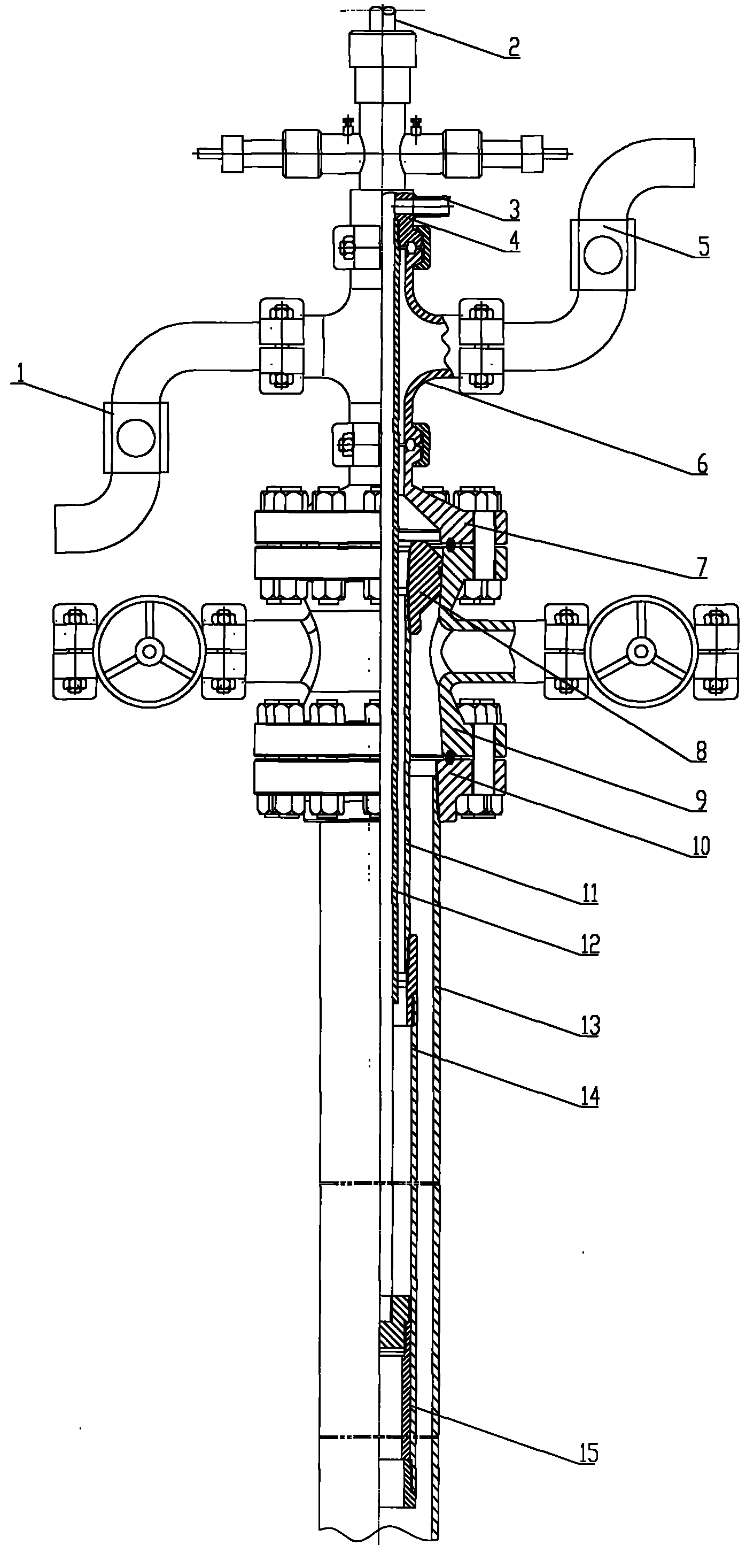
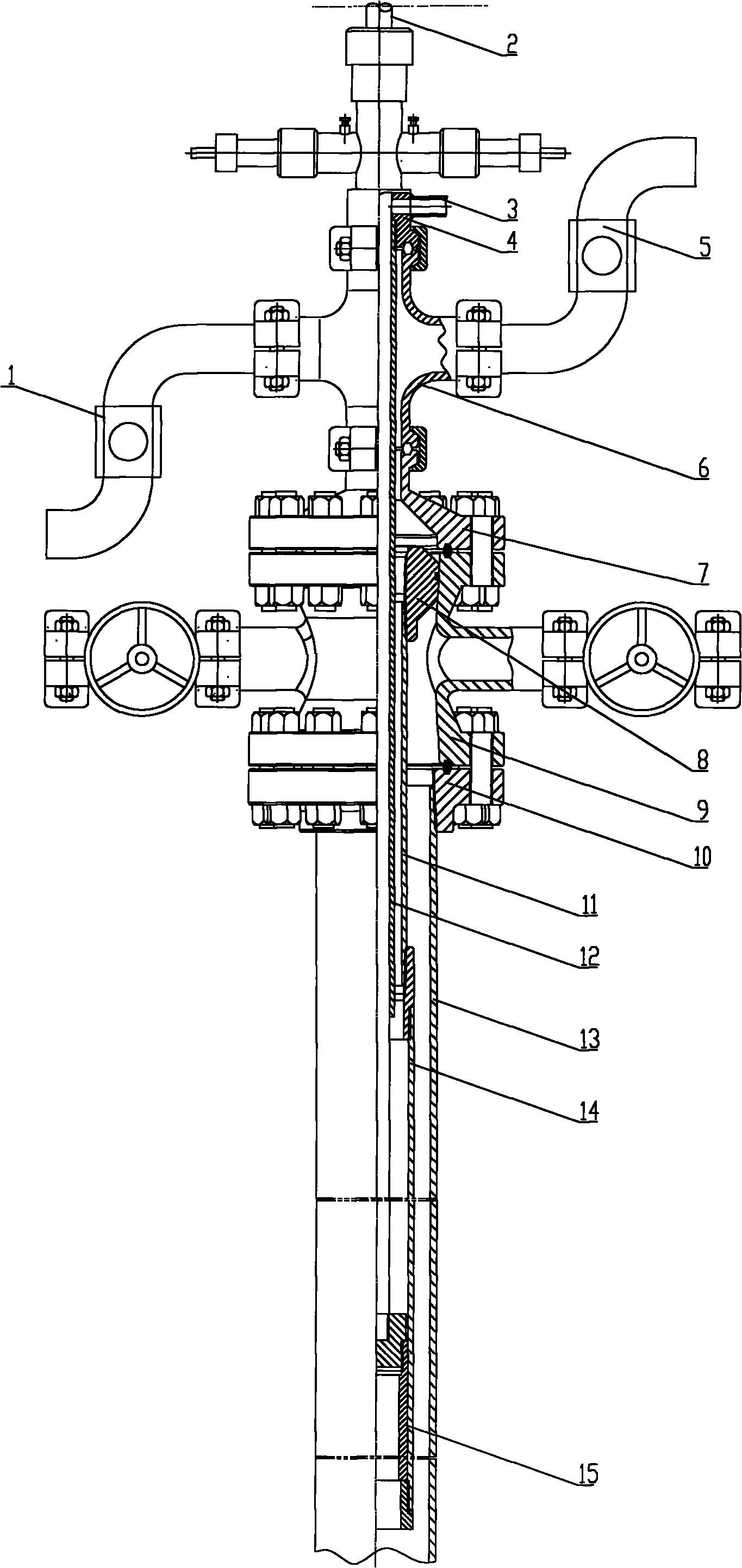
[0007] Embodiments of the present invention will be described below in conjunction with the accompanying drawings. As shown in the figure, the embodiment of the present invention consists of a liquid inlet valve 1, a polished rod 2, a pressure relief pipe 3, a sealer 4, a liquid discharge valve 5, a small cross 6, an upper flange 7, a hanger 8, and a large cross 9. Lower flange 10, inner pump barrel 11, casing 12, booster pump barrel 13, booster plunger 14, small cross 6, upper flange 7, large cross 9, lower flange 10 from the upper Connect from bottom to bottom, the upper part of the casing 12 is connected to the lower flange 10, the hanger 8 is installed in the large cross 9, and is sealed with the large cross 9, the liquid inlet valve 1 is installed on the side of the small cross 6, and the small four The drain valve 5 is installed on the other side of the passage 6, the pressure relief pipe 3 is installed at the lower part of the sealer 4, the pressure relief pipe 3 commun...


PUM


Abstract

The invention relates to a pressurized water injection device. The device comprises a small double tee, an upper flange, a large double tee, a lower flange and sleeves which are sequentially connected, wherein a hanger is arranged in the large double tee; one side of the small double tee is provided with a liquid inlet valve, while the other side is provided with a liquid outlet valve; a pressurerelief pipe is arranged on a lower part of a sealer; the pressure relief pipe is communicated with a lower inner part of the sealer; an upper part of a booster pump cylinder is connected with the hanger so that the booster pump cylinder is hung on the large double tee; the upper part of an internal pump cylinder is connected with the lower part of the hanger; a polished rod passes through the sealer; the lower part of the polished rod is connected with a pressurizing plunger which is positioned in the booster pump cylinder; the polished rod is in matched seal with the internal pump cylinder; and the upper part of the polished rod is connected with an oil pumping unit. The oil pumping unit is used for pressurizing for water injection, the pressurized water has low pulse and large fluctuation and can be used for blocking removing and dredging of a stratum layer, the penetrability of the stratum layer is improved, and the injected water amount is increased; and as the oil pumping unit iscommon equipment and has the advantages of easy management, low management difficulty, less maintenance, low labor intensity, high water injection time rate, long cycle, and obvious economic benefitsand social benefits, the oil pumping unit is used for pressurizing the injection water.

Description

technical field [0001] The invention is equipment for water injection in an oil field, and is a pressurized water injection device. Background technique [0002] Individual water injection wells require high-pressure water to be injected into the formation. Various oilfields have adopted a variety of booster equipment, such as surface plunger pumps and centrifugal pumps. These pumps are used to boost the pressure on the existing water injection pipe network and inject them into the injection water that requires high pressure. In water wells, these pressurization equipment have shortcomings, mainly because the output pressure is stable, the pressure fluctuation is small, and it is not as effective as vegetables to penetrate the formation, and it cannot improve the permeability of the water injection layer. Ground plunger pumps and centrifugal pumps are used for pressurized water injection. Due to the high inlet and high output, there are serious problems in the sealing of the...

Claims


Application Information

Patent Timeline
Patent Type & Authority Applications(China)
IPC IPC(8): E21B43/20
Inventor 雷丽郭文峰杨国峰姚燕
Owner 南通山口精工机电有限公司
Why Eureka
Try Eureka