Atomic motion simulator
A motion simulation and atomic technology, applied in the field of dynamical systems, can solve problems such as the inability to know the real structure inside the atom, the mechanism of perpetual motion inside the nucleus, etc.
- Summary
- Abstract
- Description
- Claims
- Application Information
AI Technical Summary
Problems solved by technology
Method used
Image
Examples
no. 1 example
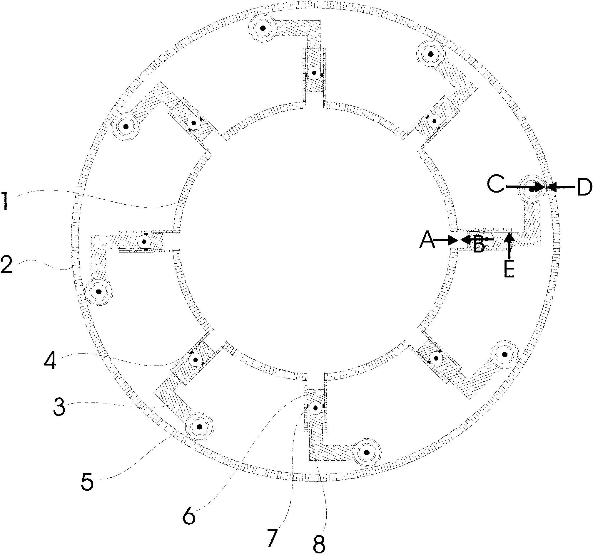
[0022] see figure 1 , this figure is a cross-sectional view of an atomic motion simulator, including a circular hydraulic system (1), a circular shell (2), a strut system (3), a hydraulic pipe (4), a wheel (5), a piston (6 ), limit ring (7), movable head (8). The cross-section of the hydraulic system and the housing is circular. The hydraulic pipe protrudes from the hydraulic system. There is a piston and a limit ring inside the hydraulic pipe. The piston has a movable head connected to the strut system. One end of the L-shaped strut has a wheel top. on the inner wall of the circular shell. There are multiple sets of strut systems and hydraulic pipes. We use arrows to indicate the mechanism of the rotation force of the atomic motion simulator: the hydraulic pressure A generates thrust on the strut through the piston, B is the reaction force of the strut to the hydraulic system, and the wheel on the elbow of the strut pushes against the inner surface of the shell , the actio...
no. 2 example
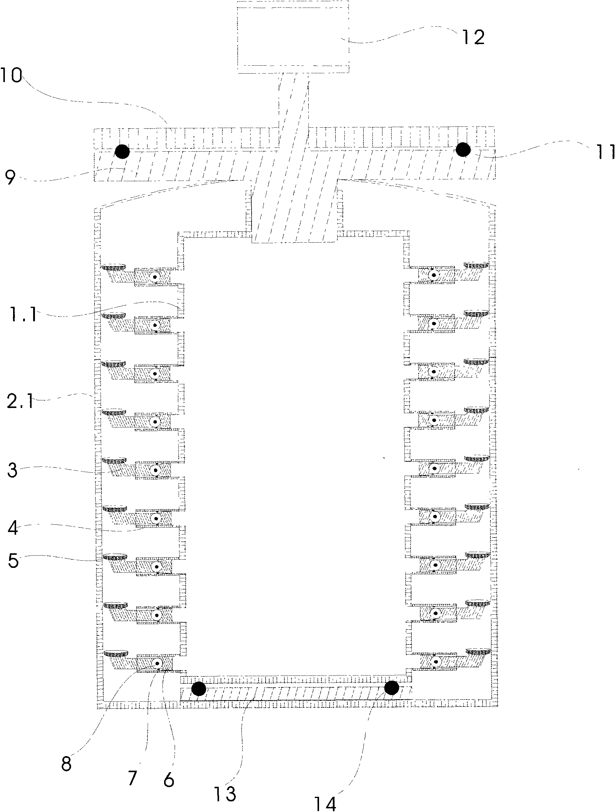
[0024] see figure 2 , this figure is a vertical section view of a cylindrical atomic motion simulator, including a cylindrical hydraulic system (1.1), a cylindrical shell (2.1), a strut system (3), a hydraulic pipe (4), a wheel (5), and a piston (6), limit ring (7), movable head (8), circular turntable piston (9), rotor on the piston turntable (11), disc cover (10), generator (12), hydraulic system bottom The turntable (13) and rotor (14). The figure shows a cylindrical atomic motion simulator with a multi-layer strut system. The rest of the undescribed parts are the same as the first embodiment and will not be repeated.
no. 3 example
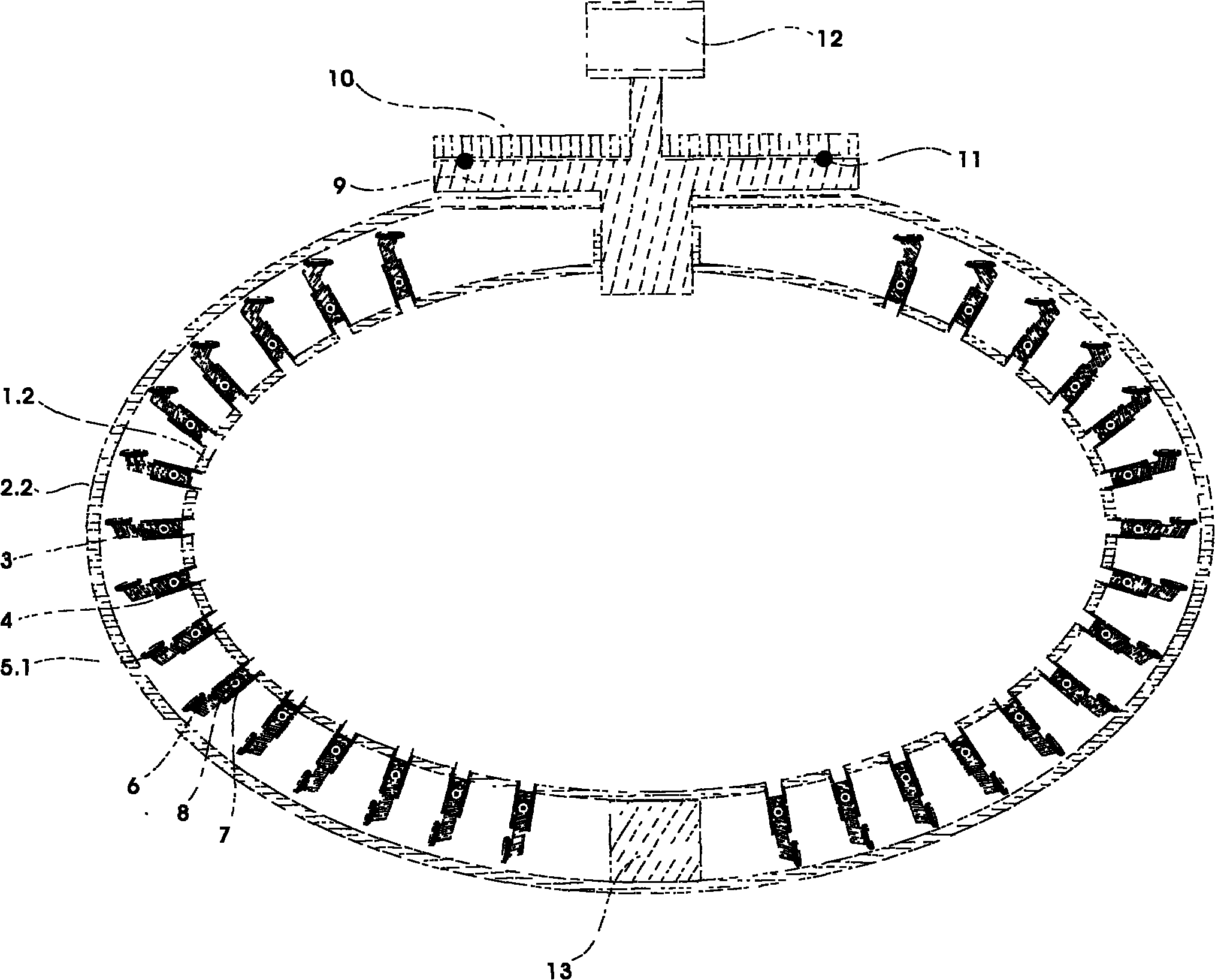
[0026] see image 3 , this figure is a vertical section view of a spherical atomic motion simulator, including a spherical hydraulic system (1.2), a spherical shell (2.2), a strut system (3), a hydraulic pipe (4), a wheel (5.1), and a piston (6), limit ring (7), movable head (8), circular turntable piston (9), rotor on the piston turntable (11), disc cover (10), generator (12), hydraulic system bottom the rotating column (13). The figure shows a spherical atomic motion simulator with a multi-layer strut system. The strut system is arranged layer by layer along the cut surface of the ball. The direction of the elbow of the strut protruding out is consistent with the cross section of the sphere. The wheels on the strut are also designed as arc-shaped cones according to the arc shape of the inner wall of the shell. The rest of the undescribed parts are the same as the first embodiment and will not be repeated.
PUM
 Abstract
Description
Claims
Application Information
 - R&D
- Intellectual Property
- Life Sciences
- Materials
- Tech Scout
- Unparalleled Data Quality
- Higher Quality Content
- 60% Fewer Hallucinations
Browse by: Latest US Patents, China's latest patents, Technical Efficacy Thesaurus, Application Domain, Technology Topic, Popular Technical Reports.
© 2025 PatSnap. All rights reserved.Legal|Privacy policy|Modern Slavery Act Transparency Statement|Sitemap|About US| Contact US: help@patsnap.com


