Laminated spray head
A layered, spray head technology, applied in the direction of spray devices, spray devices, etc., can solve problems such as uneven water spray
- Summary
- Abstract
- Description
- Claims
- Application Information
AI Technical Summary
Problems solved by technology
Method used
Image

Examples
Embodiment 1
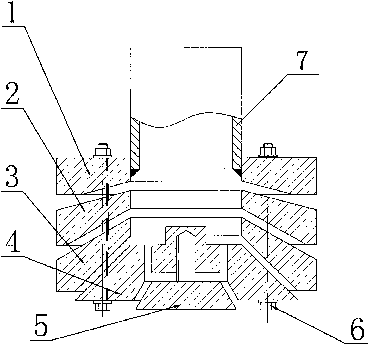
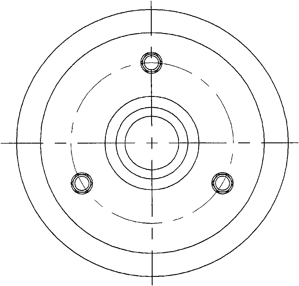
[0014] Embodiment 1, the fixed disc 1 of the present invention is fixedly installed on the lower end of the connecting pipe 7, the fixed disc 1 is provided with 2 or more through holes, and the center of the fixed disc 1 is the inner part of the connecting pipe 7. The cavity is connected to the through hole, and the thickness of the inner ring of the fixed disc 1 is smaller than the thickness of the outer ring to form a downward-sloping disc-shaped structure; one or more downward-sloping middle discs are installed in a gap fit at the lower part of the fixed disc 1. The disc 2 is provided with a through hole matched with the central through hole of the fixed disc 1 in the center of the middle disc 2; the center nozzle 4 is installed at the bottom of the middle disc 2; the middle disc 2 and the center nozzle 4 are provided with The through holes corresponding to the through holes provided on the fixed disc 1, bolts or screw rods 6 respectively pass through the through holes on th...
Embodiment 2
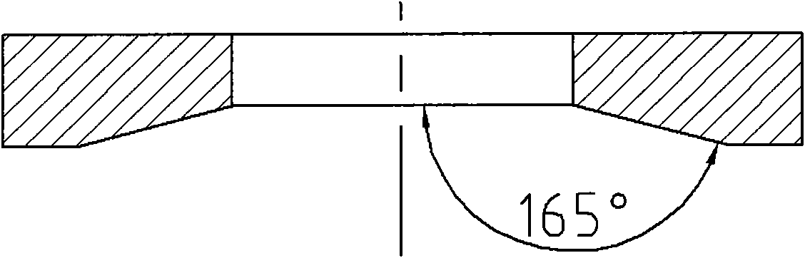
[0015] Embodiment 2, in order to orientate the direction of spraying water, the present invention also can make the inclination angle of the upper part of the middle disc 2 smaller than the inclination angle of the lower part, forming a slanted downward spray around. In order to better ensure the gap, the upper inclination angle of the middle disc 2 is the same as the lower inclination angle of the fixed disc 1 or the upper adjacent intermediate disc. The central nozzle 4 can be made into a closed truncated cone shape, and at the same time, spray holes are arranged on the plane of the truncated cone, mainly downward spray holes are arranged to form a downward shower. refer to Figure 1 to Figure 7 , all the other are with embodiment 1.
Embodiment 3
[0016] Embodiment 3, in order to achieve a better spraying effect at the lower part, the present invention can also set a plug 5 at the lower part of the central nozzle 4 . The plug 5 can be made into a truncated cone with a small upper part and a larger lower part, the lower end is flat, and the upper part is a screw structure; the lower part of the central nozzle 4 is provided with a conical cavity that matches the upper conical surface of the plug 5, and the lower part of the central nozzle 4 A screw hole is established in the center, and the upper screw rod of the plug 5 is sleeved in the central screw hole at the bottom of the central nozzle 4 . refer to Figure 1 to Figure 7 , and the rest are the same as the above-mentioned embodiment.
PUM
 Abstract
Description
Claims
Application Information
 - R&D
- Intellectual Property
- Life Sciences
- Materials
- Tech Scout
- Unparalleled Data Quality
- Higher Quality Content
- 60% Fewer Hallucinations
Browse by: Latest US Patents, China's latest patents, Technical Efficacy Thesaurus, Application Domain, Technology Topic, Popular Technical Reports.
© 2025 PatSnap. All rights reserved.Legal|Privacy policy|Modern Slavery Act Transparency Statement|Sitemap|About US| Contact US: help@patsnap.com