
Continuous inflatable air sealing member and manufacturing method thereof

A technology of air sealing body and manufacturing method, which is applied in packaging and other directions, can solve the problems of inconvenient inflation operation, cumbersome manufacturing, poor inflation efficiency, etc., and achieve the effect of saving inflation time

Active Publication Date: 2010-09-29
KUNSHAN AIRBAG PACKING CORP
View PDF1 Cites 12 Cited by
  • Summary
  • Abstract
  • Description
  • Claims
  • Application Information

AI Technical Summary

Problems solved by technology

However, due to the fact that each check valve is independent of each other in this structure, each air column is inflated separately, and multiple air columns cannot be inflated at the same time. Moreover, it is quite cumbersome to manufacture, and each check valve must be placed one by one. The heat-sealed connection is made at the predetermined position in the air column. Once the position of the check valve or the connection position of the heat-sealed mold is shifted, the check valve cannot be fixed in the air column, or the inlet at the top exceeds the heat-sealed mold The connected heat seal line will cause the gas to be filled into the inflatable channel. Although the inflatable channel expands, the check valve cannot be opened with the expansion of the inflatable channel, resulting in the problem that the gas cannot be filled into the air column.
[0004] In another air sealing body structure, the switch for air entering the sealing body adopts the form of two inner membranes and one outer membrane connected to each other to form a switch valve passage. When inflated, the sealing body expands to block the passage. The on-off valve is mainly used to block the air in the sealing body from leaking out, but when the air inlet channel is filled with gas and expands, even if the two outer membranes are pushed apart by the gas, the on-off valve will not follow The two outer membranes move and pull apart, so the two inner membranes of the switch valve are still attached together and cannot open the air passage inlet. According to its design, air cannot automatically enter the sealing body
[0005] In addition, in the air-tight body of the prior art, the air inlet at the top of the check valve is narrow, and its width is smaller than the width of the air column. Therefore, when inflating, the inflating device must be aligned with the air inlet, which is not only inconvenient for the inflation operation , and too small air inlet structure will result in poor inflation efficiency

Method used


Image

  • Continuous inflatable air sealing member and manufacturing method thereof
  • Continuous inflatable air sealing member and manufacturing method thereof
  • Continuous inflatable air sealing member and manufacturing method thereof

Examples


Embodiment Construction

[0070] In order to make the object, technical solution and advantages of the present invention clearer, the present invention will be described in detail below with reference to the accompanying drawings and specific embodiments.

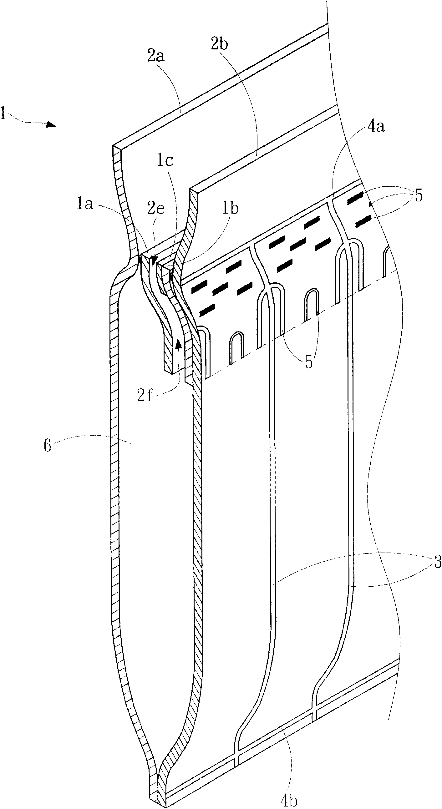
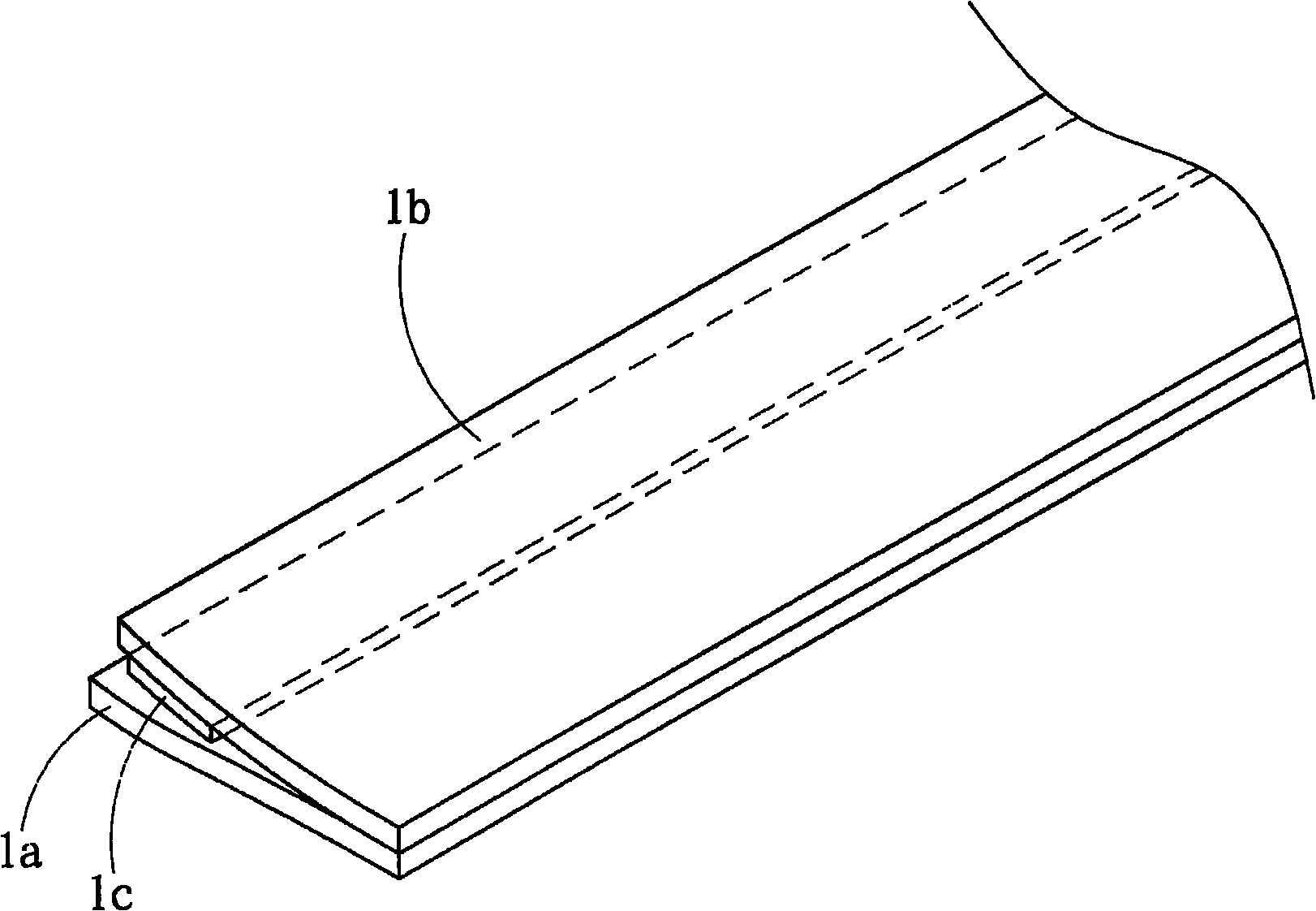
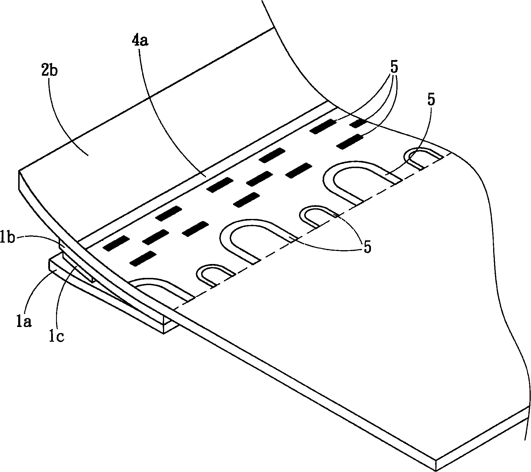
[0071] see figure 1 , Figure 2A , Figure 2B , Figure 2C , image 3 , Figure 4 and Figure 5 As shown, it is used to illustrate the structure of the continuous inflatable air sealing body described in the first embodiment of the present invention.

[0072] The continuous inflatable air sealing body 1 of the present invention includes: a first outer film 2a and a second outer film 2b, two inner films 1a and 1b, a plurality of channel adhesive parts 5, a gas channel 2f, and a plurality of first heat-sealing lines 3. Two second heat-sealing lines 4a and 4b, and multiple air columns 6.

[0073] Wherein the first outer membrane 2a and the second outer membrane 2b are superimposed on each other.

[0074] The two inner membranes 1a and 1b are in...


PUM


Abstract

The invention provides a continuous inflatable air sealing member and manufacturing method thereof. In the air sealing member, a plurality of channel adhering parts are adhered with two inner membranes to form a plurality of gas channels, and a plurality of first heat sealing lines are adhered with a first outer membrane and a second outer membrane and the two inner membranes along a first direction, two second heat sealing lines are adhered along a second direction, wherein one second heat sealing line is adhered with the first outer membrane and the second outer membrane, the other second heat sealing line is adhered with the first outer membrane and adjacent inner membrane as well as the second outer membrane and adjacent inner membrane, so that the two inner membranes are not adhered at the second heat sealing line and a plurality of air inlets are formed, a plurality of air columns are formed among the first outer membrane, the second outer membrane and the two inner membranes which are adhered with the first heat sealing line and the second heat sealing line, gas flows into the gas channel by virtue of the air inlet and is filled into the air column for aeration and expansion, the gas presses one end of the two inner membranes to be adhered after entering the air column, thus sealing the air column, and the other end of the two inner membranes are separated to form a gap. The air sealing member can automatically open the air inlet and continuous aeration is realized.

Description

technical field [0001] The invention relates to an air sealing body and a manufacturing method thereof, in particular to a continuous inflatable air sealing body and a manufacturing method thereof. Background technique [0002] The air-sealed body is made of resin film, which is heat-sealed to form an air column in a sealed state, and is equipped with an inflation port for inflation. When the gas is filled into the air column through the inflation port, the air-sealed body can be used for inner packaging as a buffer material. [0003] In an air-tight body structure in the prior art, each air column is respectively provided with independent check valves, and the inlet at the top of each check valve is aligned with the heat sealing line and connected together. After entering the inflatable channel, the inflatable channel expands to open the check valve so that the gas can be charged into the air column. However, due to the fact that each check valve is independent of each ot...

Claims


Application Information

Patent Timeline
Patent Type & Authority Applications(China)
IPC IPC(8): B65D81/17B29C65/48
Inventor 廖建华廖耀鑫廖国雄
Owner KUNSHAN AIRBAG PACKING CORP
Learn More