Road illuminating system

A lighting system and road technology, applied in lighting devices, fixed lighting devices, lighting and heating equipment, etc., can solve problems such as poor lighting utilization, and achieve the effect of reducing lighting energy consumption and improving lighting efficiency.

Inactive Publication Date: 2010-09-29
李元骏
View PDF3 Cites 3 Cited by
  • Summary
  • Abstract
  • Description
  • Claims
  • Application Information

AI Technical Summary

Problems solved by technology

[0003] In order to overcome the problem of poor lighting utilization rate of the existing road lighting system, the present invention provides a road lighting system, which can not only be based on time and ambient illuminance, but also on the basis of traffic conditions, that is, the traffic conditions of pedestrians and vehicles. Automatically adjust lighting methods to provide real-time optimized lighting solutions

Method used


Image

  • Road illuminating system
  • Road illuminating system

Examples


Embodiment Construction

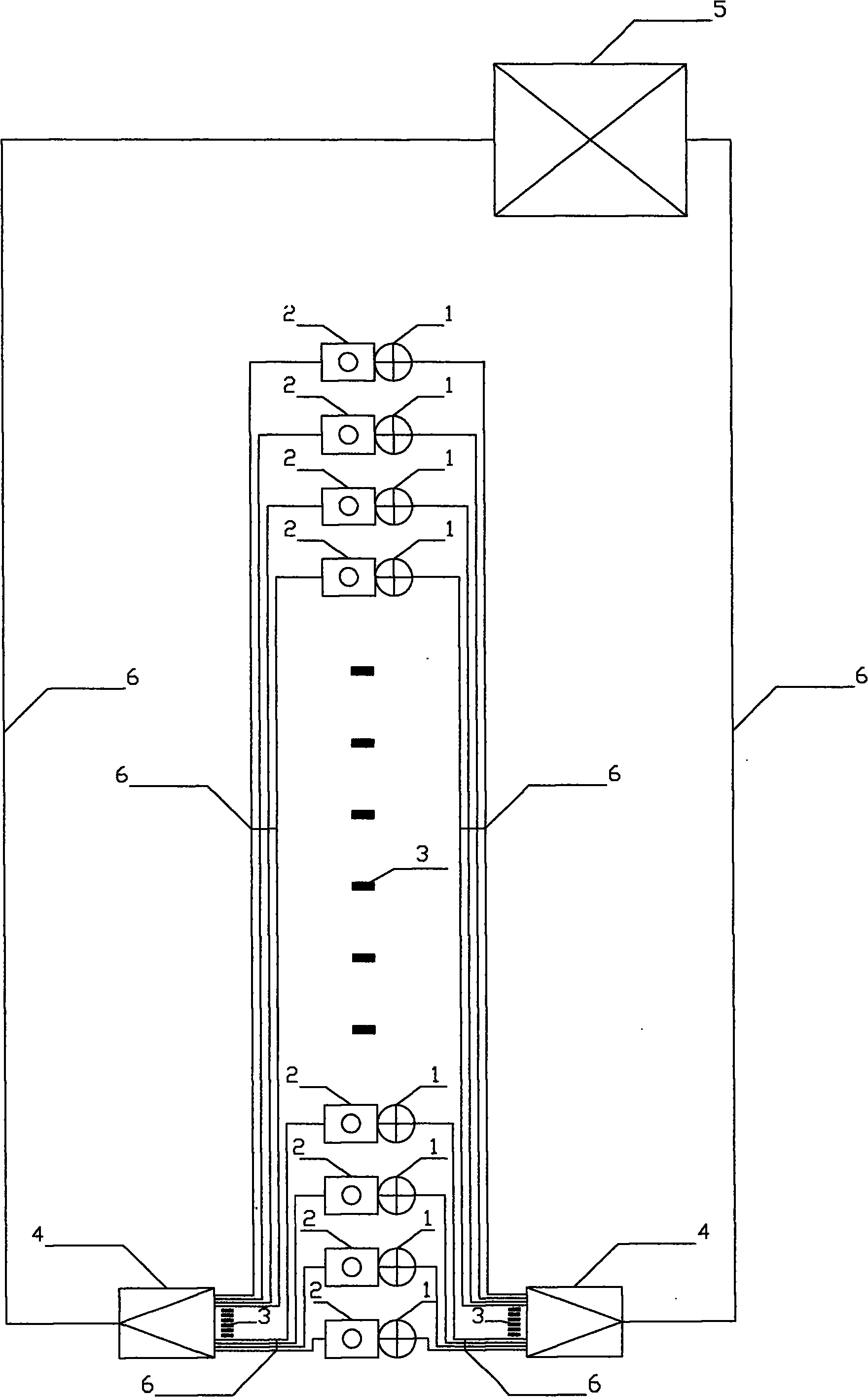
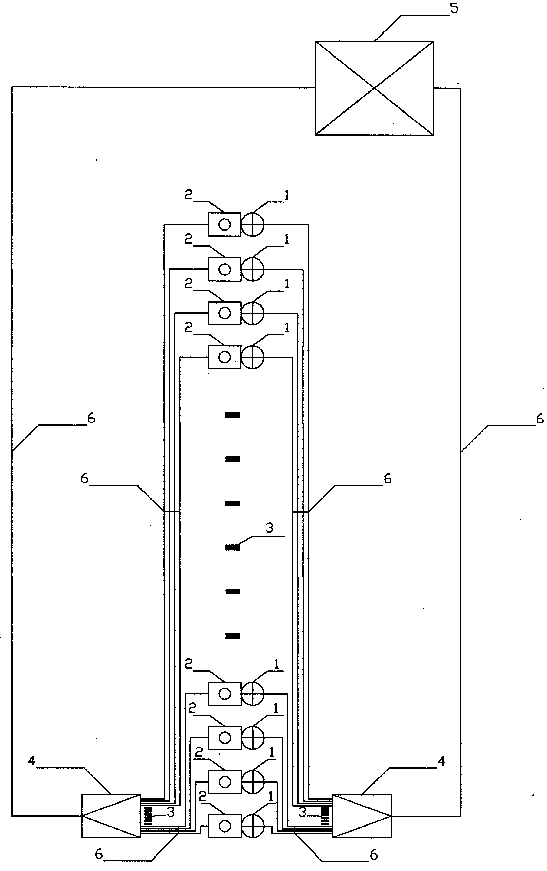
[0009] In the figure, the sensor (2) is connected to the main controller (5) through the data line (6) and the line collecting device (4), and the main controller continuously monitors the signal fed back by the sensor. Each sensor monitors the road segment within its respective range. The main controller monitors each sensor. When the sensor (2) finds pedestrians or vehicles, the main controller (5) calculates the appropriate lighting opening range according to the preset program - for motor vehicle lanes, take the road section with a speed limit of 100km / h as an example, its safe The distance between vehicles is 100m. Considering the system delay and the speeding of some vehicles, at least turn on the road lighting within the range of 200m from the position where the sensor finds the target to its front. For pedestrians and non-motor vehicles, considering the uncertainty of their direction of travel, the road lighting within 100m before and after the target can be turned on...


PUM


Abstract

The invention relates to a road illuminating system which can automatically adjust an illuminating way according to the passing condition of pedestrians and vehicles. The system comprises a sensor, a main controller, a controllable road illuminating lamp, a data line (6) and a line collecting device (4), wherein the data line (6) and the line collecting device (4) are matched with the controllable road illuminating lamp; and the sensor in the system can recognize the pedestrians and the vehicles, and the road illuminating lamp in the system can be controlled, repeatedly started in short time or adjusted with power. The system adopts that whether the pedestrian or the vehicle passes or not as one of the judging condition for that whether the road illuminating lamp is required to be started or not; the road illumination is started at the positions with the pedestrian and the vehicle; and the road illumination is turned off or the illuminating level is reduced to a degree at the positions without the pedestrian and the vehicle.

Description

Technical field [0001] The invention relates to a road lighting system capable of automatically adjusting the lighting mode according to the passing conditions of pedestrians and vehicles. Background technique [0002] At present, the control mode of the existing road lighting system is generally switch type. Most road lighting systems use time as the basis and switch on and off according to the preset time; a few road lighting systems use the ambient illuminance as the basis for judging whether to turn on the lights. The existing problem is: under the condition of low traffic flow in the middle of the night, the lighting utilization rate is poor, resulting in a lot of waste of electric energy. Even on the basis of the existing system, it is still impossible to fundamentally solve this problem by reducing the energy consumption of late-night lighting through sub-circuit control and the use of dimmable ballasts. And it will further lead to the problem of insufficient lighti...

Claims


Application Information

Patent Timeline
Patent Type & Authority Applications(China)
IPC IPC(8): F21S8/00F21V23/00H05B37/02
CPCY02B20/42Y02B20/40
Inventor 李元骏
Owner 李元骏
Why Eureka
Try Eureka