Thin film type white light LED chip

An LED chip and thin-film technology, applied in electrical components, electrical solid devices, circuits, etc., can solve the problems of complex driving circuit design, low efficiency of white LEDs, and complicated device preparation processes, and achieve overall external quantum efficiency improvement. The actual utilization rate and the effect of reducing lighting energy consumption

Active Publication Date: 2020-05-26
SOUTH CHINA UNIV OF TECH
View PDF6 Cites 1 Cited by
  • Summary
  • Abstract
  • Description
  • Claims
  • Application Information

AI Technical Summary

Problems solved by technology

However, the external quantum efficiency of blue and violet LEDs is low, and the fluorescent quantum efficiency of phosphor powder is less than 100%, which seriously affects the overall efficiency of white LEDs, making the efficiency of white LEDs in the form of "electric + photoinduced" even lower.
In addition, only for plan B, the strong ultraviolet components in its spectrum are harmful to the human body, especially in the case of long-term exposure. Therefore, considering the impact of ultraviolet rays on the human body, the In the current white light implementation, using blue LED chips to excite red and green (or yellow) phosphors (Scheme A) is still the first choice for commercial white LEDs, despite its low efficiency
[0006] see again figure 1 , for solution C, although this method can obtain high-efficiency white LED chips, the device preparation process is complicated, and the entire chip involves more than ten layers of thin film deposition processes, and the cost is very high
For solution D, since the red, green and blue LEDs all require independent driving circuits, the number of driving circuits for each white LED is increased to three sets, and the driving circuit design is complicated, which also requires very high cost, and at the same time sacrifices the horizontal size, usually not used as a lighting element
Due to the problem of preparation cost, the market share of the two white lighting solutions in Scheme C and Scheme D is very low

Method used


Image

  • Thin film type white light LED chip
  • Thin film type white light LED chip
  • Thin film type white light LED chip

Examples


Embodiment Construction

[0036] Embodiments of the present invention will now be described with reference to the drawings, in which like reference numerals represent like elements.

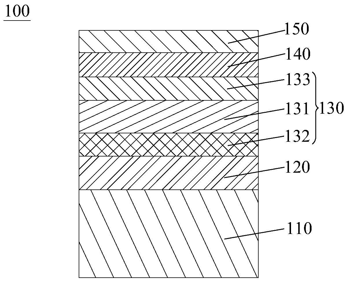
[0037] Combine first Figure 3a-Figure 4b As shown, the thin-film white LED chip 100 provided by the present invention includes a transparent substrate 110 , a first transparent electrode 120 , a light emitting structure 130 , a second transparent electrode 140 and a first phosphor layer 150 arranged in sequence. Wherein, the light-emitting structure 130 includes a light-emitting layer 131 and a hole injection layer 132 and an electron injection layer 133 disposed on both sides thereof, and the total thickness of the electron injection layer 133 and the second transparent electrode 140 (inverted structure) or hole The total thickness of the injection layer 132 and the second transparent electrode 140 (upright structure) is less than one light emitting wavelength of the light emitting layer 131 (details will be described l...


PUM

PropertyMeasurementUnit
wavelengthaaaaaaaaaa
thicknessaaaaaaaaaa
thicknessaaaaaaaaaa

Abstract

The invention discloses a thin film type white light LED chip. The thin film type white light LED chip comprises a transparent substrate, a first transparent electrode, a light-emitting structure, a second transparent electrode and a first fluorescent powder layer which are arranged in sequence, wherein the light-emitting structure comprises a light-emitting layer, an electron injection layer anda hole injection layer, the electron injection layer and the hole injection layer are arranged on the two sides of the light-emitting layer, and the total thickness (inverted structure) of the electron injection layer and the second transparent electrode or the total thickness (upright structure) of the hole injection layer and the second transparent electrode is less than the length of the light-emitting wavelength of the light-emitting layer. Through the arrangement of the second transparent electrode, photons emitted by the light-emitting layer are enabled to have an opportunity to permeateinto the first fluorescent powder layer; and the total thickness (inverted structure) of the electron injection layer and the second transparent electrode or the total thickness (upright structure) of the hole injection layer and the second transparent electrode is less than the length of one light-emitting wavelength of the light-emitting layer, so that an evanescent wave generated by total reflection can permeate into the first fluorescent powder layer and is absorbed by the first fluorescent powder layer to emit light, so that the overall external quantum efficiency of the LED chip is improved.

Description

technical field [0001] The invention relates to the technical field of light-emitting diodes (LEDs), in particular to a thin-film white LED chip with high external quantum efficiency and low production cost. Background technique [0002] White light lighting is closely related to the work and life of human beings. White light lighting technology has been greatly developed so far. Among them, white light-emitting diodes (LEDs) have become one of the best choices to replace traditional lighting components (such as incandescent lamps and fluorescent lamps). Using green, Energy-saving and environmentally friendly white LEDs are also the general trend as the main lighting components. Thin-film white LEDs will gradually replace LEDs due to the fact that the thickness of each layer is on the order of nanometers, the amount of materials used is small, and it is also compatible with processes such as scraping and printing, and the cost is lower. Traditional white LEDs emitted by poi...

Claims


Application Information

Patent Timeline
Patent Type & Authority Applications(China)
IPC IPC(8): H01L33/20H01L33/38H01L33/42H01L33/50H01L51/50H01L51/52
CPCH01L33/42H01L33/38H01L33/50H01L33/20H01L33/504H10K50/115H10K50/125H10K50/17H10K50/171H10K50/805
Inventor 陈梓铭叶轩立黎振超曹镛
Owner SOUTH CHINA UNIV OF TECH
Why Eureka
Try Eureka