Color conversion member and light emitting apparatus using the color conversion member

a technology of color conversion and light emitting apparatus, which is applied in the direction of optical radiation measurement, instruments, spectrometry/spectrophotometry/monochromators, etc., can solve the problems of inability to apply to a practical use, insufficient restrain the degradation of the emission brightness of the light emitting apparatus has a considerably low luminous efficiency, etc., to achieve excellent characteristics, reduce the emission of fluorescence, and improve the external quantum efficiency

Inactive Publication Date: 2009-09-10
SHARP KK
View PDF6 Cites 40 Cited by
  • Summary
  • Abstract
  • Description
  • Claims
  • Application Information

AI Technical Summary

Benefits of technology

[0022]A high-efficiency color conversion member achieved by restraining the fluorescence emitted from a certain phosphor from being absorbed again by another different phosphor, as well as a light emitting apparatus including the color conversion member can be provided. This is for the reason that the color conversion member of the present invention can utilize the total reflection at the interface between the light transmissive members to restrain the fluorescence emitted from an N-th phosphor from being absorbed again by the N−1-th phosphor, so that the external quantum efficiency is improved.
[0023]The light emitting apparatus of the present invention exhibits excellent characteristics such as low-voltage drive, small size and lightweight, high durability and long life, and therefore, the apparatus is widely applicable to the backlight for the liquid crystal display and the illumination apparatus for example.

Problems solved by technology

The above-described conventional methods, however, cannot sufficiently restrain degradation of the emission brightness of the light emitting apparatus due to the fact that the fluorescence generated from a certain phosphor is absorbed by another different phosphor.
Since the phosphor isotropically emits fluorescence, the above-described structure cannot solve the problem that the fluorescence emitted from the green- and blue-emission phosphors toward the light emitting device is absorbed by the red-emission phosphor.
Therefore, the resultant light emitting apparatus has a considerably low luminous efficiency and cannot be applied to a practical use.

Method used


Image

  • Color conversion member and light emitting apparatus using the color conversion member
  • Color conversion member and light emitting apparatus using the color conversion member
  • Color conversion member and light emitting apparatus using the color conversion member

Examples


example 1

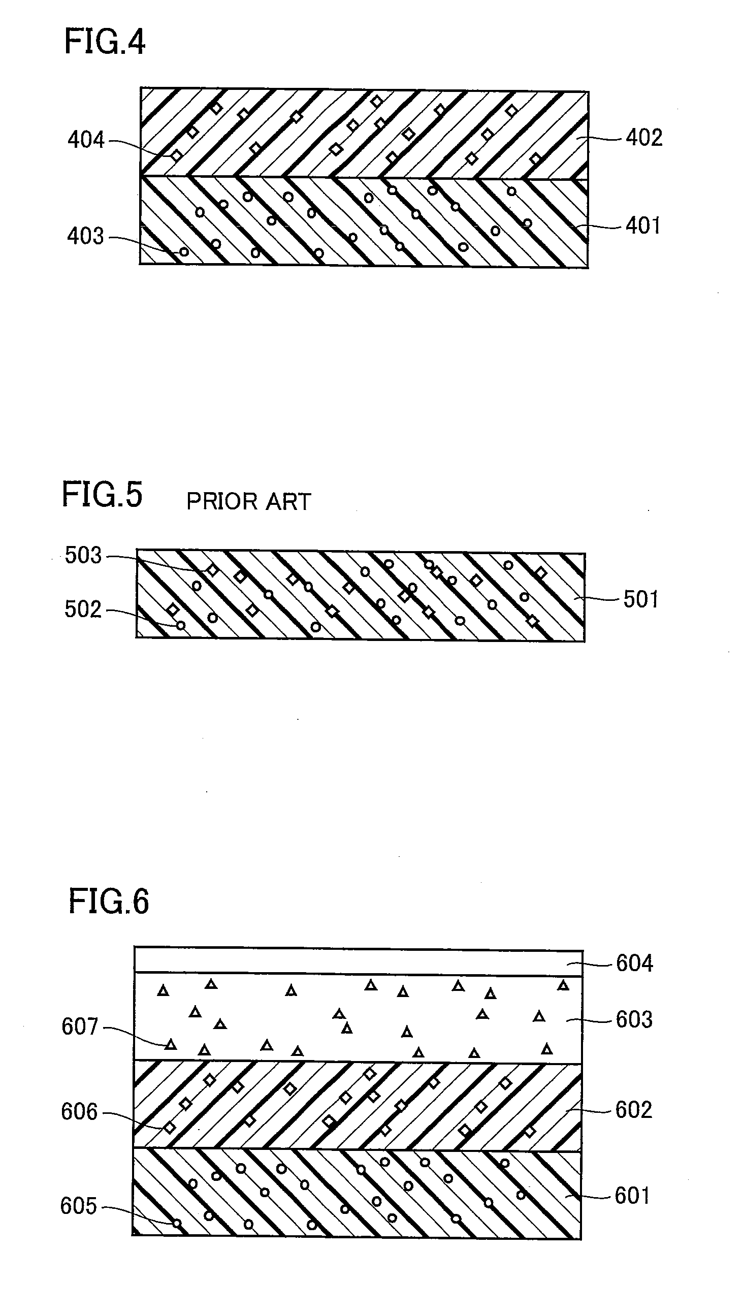
[0085]FIG. 4 shows a schematic cross section of a color conversion member according to Example 1, which will be described hereinafter with reference to FIG. 4.

[0086]The color conversion member of the present example includes a first light transmissive member 401 containing a first phosphor 403 illuminated with an excitation light to emit a red fluorescence, and a second light transmissive member 402 containing a second phosphor 404 illuminated with an excitation light to emit a green fluorescence, and the first and second light transmissive members are stacked in order. A method for manufacturing the color conversion member will be described.

[0087]First, a slurry was prepared by sufficiently mixing a silicone resin (refractive index 1.45) with 1.4% by mass, with respect to the silicone resin, of CaAlSiN3:Eu, namely first phosphor 403 emitting a red fluorescence with a wavelength of 651 nm. The slurry was then poured into a plate-like mold. After poured, the slurry was heated at 150°...

example 2

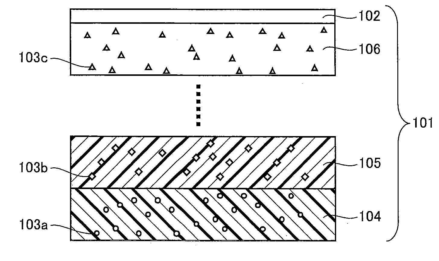
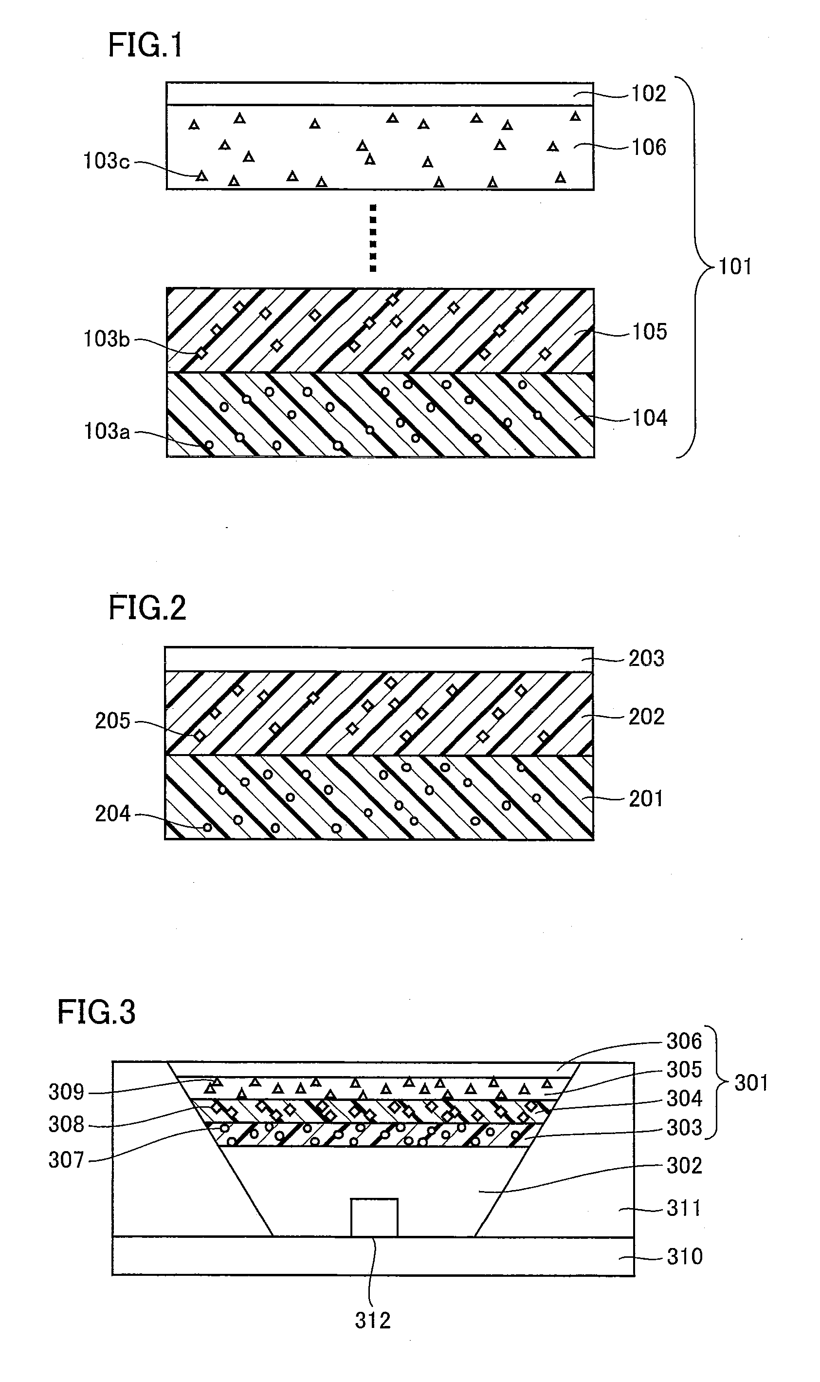
[0094]Example 2 will be described hereinafter with reference to above-described FIG. 2. In connection with the present example, a description will be given of a color conversion member having a stack structure made up of two different light transmissive members with different refractive indices respectively where one of the light transmissive members having a larger refractive index than the other is covered with another light transmissive member having a smaller refractive index than the aforementioned larger refractive index.

[0095]As first phosphor 204, red emission phosphor CaAlSiN3:Eu with an emission wavelength of 651 nm was used and, as second phosphor 205, green emission phosphor Ca3(Sc, Mg)2Si3O12:Ce with an emission wavelength of 512 nm was used. A silicone resin (refractive index 1.45) was used for first light transmissive member 201, and an epoxy resin (refractive index 1.59) was used for second light transmissive member 202. A similar method to Example 1 was used to prod...

example 3

[0097]FIG. 6 shows a schematic cross section of a color conversion member according to Example 3, which will be described hereinafter with reference to FIG. 6.

[0098]Red emission phosphor CaAlSiN3:Eu with an emission wavelength of 651 nm was used as a first phosphor 605, green emission phosphor SrA2O4:Eu with an emission wavelength of 518 nm was used as a second phosphor 606, and blue emission phosphor BaMgAl10O17:Eu with an emission wavelength of 450 nm was used as a third phosphor 607.

[0099]As a first light transmissive member 601, a second light transmissive member 602, a third light transmissive member 603, and a light transmissive member 604, a silicone resin (refractive index 1.45), an acrylic resin (refractive index 1.49), an epoxy resin (refractive index 1.59), and a silicone resin (refractive index 1.45) were used respectively. A similar method to Example 1 was used to produce a color conversion member.

[0100]The color conversion member thus obtained was excited with light ha...


PUM


Abstract

A color conversion member of a high efficiency achieved by restraining fluorescence emitted from a certain phosphor from being absorbed again by another different phosphor, as well as a light emitting apparatus including the color conversion member are provided. The color conversion member includes N light transmissive members each containing a different one of N different phosphors illuminated with excitation light to emit fluorescence in a visible wavelength region, and the N light transmissive members are stacked in order (N is a natural number of not less than two). The color conversion member is designed in such a manner that the refractive index increases in the thickness direction while the fluorescence wavelength decreases in the thickness direction.

Description

[0001]This nonprovisional application is based on Japanese Patent Application No. 2008-050180 filed on Feb. 29, 2008 with the Japan Patent Office, the entire contents of which are hereby incorporated by reference.BACKGROUND OF THE INVENTION[0002]1. Field of the Invention[0003]The present invention relates to a color conversion member containing a phosphor and to a light emitting apparatus using the color conversion member. More specifically, the invention relates to a color conversion member absorbing an excitation light of a short wavelength to emit light of a longer wavelength than the absorbed wavelength, and to a light emitting apparatus having a combination of the color conversion member and an excitation light source.[0004]2. Description of the Background Art[0005]Recently, a light emitting apparatus has been proposed that can generate a white light by mixing the light emitted from a light emitting diode device with the fluorescence that is emitted from a phosphor absorbing a ...

Claims


Application Information

Patent Timeline
Patent Type & Authority Applications(United States)
IPC IPC(8): H05B33/00B82Y20/00C09K11/59C09K11/64H01J40/14H01L33/48H01L33/50H01L33/54H01L33/56H01L33/60H01S5/022
CPCC09K11/7721C09K11/7734C09K11/7739C09K11/774H05B33/10C09K11/7789C09K11/7792H01L33/502C09K11/7769C09K11/77348
Inventor KINOMOTO, JUNICHISAITO, HAJIME
Owner SHARP KK
Why Eureka
Try Eureka