Device and method for monitoring corrosion of buried steel pipelines

A corrosion monitoring and pipeline technology, which is applied in measuring devices, weather resistance/light resistance/corrosion resistance, current density measurement, etc., can solve problems such as cross point induction corrosion, failure to test, corrosion perforation, etc., and achieve the effect of avoiding wiring

Inactive Publication Date: 2010-09-29
许丽涛
View PDF4 Cites 6 Cited by
  • Summary
  • Abstract
  • Description
  • Claims
  • Application Information

AI Technical Summary

Problems solved by technology

This method has the following disadvantages: 1. Most buried pipelines are not equipped with test piles, so the above tests cannot be performed; 2. Even if test piles are installed, they are generally installed every 1 kilometer, so the test result is that 1 kilometer pipeline is induced corrosion The average result of the risk cannot reflect the risk of a specific position in the pipeline, and the induced corrosion failure is usually caused by severe corrosion and perforation in a certain part of the pipeline
This phenomenon is especially obvious when the overhead high-voltage transmission line intersects with the buried oil and gas transmission pipeline, because the pipeline at the intersection point is the closest to the interference source, so the electric (magnetic) field strength is significantly higher than other parts, but because the traditional test cannot realize Fixed-point monitoring, the average result of 1 km often shows that the risk of corrosion is not large, but the excavation results may indicate that severe induction corrosion has occurred at the intersection, so the existing detection technology cannot meet the requirements of use, and it is urgent to develop a device capable of fixed-point monitoring

Method used


Image

  • Device and method for monitoring corrosion of buried steel pipelines
  • Device and method for monitoring corrosion of buried steel pipelines
  • Device and method for monitoring corrosion of buried steel pipelines

Examples


Embodiment Construction

[0027] The present invention is described below in conjunction with accompanying drawing.

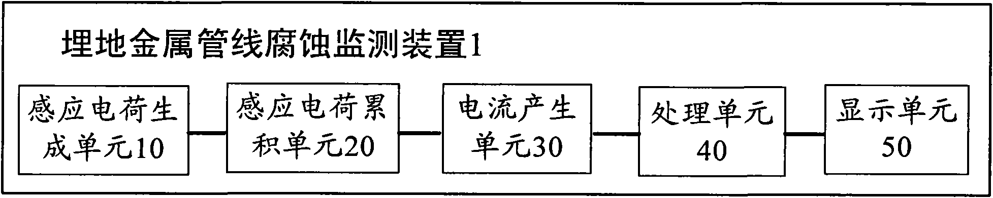
[0028] figure 1 It is a block diagram of an embodiment of the buried metal pipeline corrosion monitoring device 1 according to the present invention. Such as figure 1 As shown, the buried metal pipeline corrosion monitoring device 1 includes an induced charge generation unit 10 , an induced charge accumulation unit 20 , a current generation unit 30 , a processing unit 40 and a display unit 50 connected in sequence.

[0029]Wherein the induced charge generating unit 10 is used to generate induced charges, which are buried in the soil near the pipeline to be monitored, preferably directly above the pipeline and 1-2 cm away from the pipeline. The induced charge generating unit 10 is in the same electromagnetic field environment as the pipeline to be monitored, and it includes a metal rod with an insulating layer on the surface, and the metal rod will generate induced charges in the elect...


PUM


Abstract

The invention discloses a method for monitoring corrosion of buried steel pipelines, comprising the following steps: embedding an inductive charge generating unit (10) in soil above a pipeline to be monitored so as to enable the inductive charge generating unit (10) to be in the same electromagnetic field environment with the pipeline so as to generate inductive charge; accumulating inductive charge generated by the inductive charge generating unit (10) repeatedly through an inductive charge accumulating unit (20); generating current by a current generating unit (30) by using the accumulated inductive charge of the inductive charge accumulating unit (20); processing the current generated by the current generating unit (30) in real time through a processing unit (40) so as to generate current density and find out the maximum instantaneous current density; and displaying the maximum instantaneous current density obtained by the processing unit (40) through a display unit (50). The invention also discloses a device for monitoring corrosion of the buried steel pipelines.

Description

technical field [0001] The invention relates to the field of metal corrosion monitoring, in particular to a device and method for monitoring corrosion of buried metal pipelines. Background technique [0002] With the increasing demand for power supply, a large number of ultra-high voltage and ultra-high voltage AC and DC transmission lines have been built. The electric (magnetic) fields generated by these lines will induce a large amount of charge on the adjacent buried metal pipelines. For buried steel oil and gas transmission pipelines, since the newly built pipelines in the past 20 years basically adopt three layers of PE anti-corrosion coating with good insulation performance, it is easier to cause the accumulation of induced charges; when there is a small damage to the anti-corrosion coating, Due to the low grounding resistance of the damaged point, the induced charge will flow to the ground through the damaged point. At the same time, due to the small window area, the ...

Claims


Application Information

Patent Timeline
Patent Type & Authority Applications(China)
IPC IPC(8): G01N17/02G01R19/08
Inventor 许丽涛
Owner 许丽涛
Why Eureka
Try Eureka