
Moss clearing conveyor

A technology of clearing machine and moss, which is applied in the field of clearing machine, can solve the problems of waste of manpower and material resources, slow clearing speed, etc., and achieve the effect of thorough clearing, convenient operation and saving manpower and material resources

Inactive Publication Date: 2010-10-06
王丽瑛
View PDF0 Cites 16 Cited by
  • Summary
  • Abstract
  • Description
  • Claims
  • Application Information

AI Technical Summary

Benefits of technology

This technology makes it easier than ever before people start working with machines like handheld tools or electric drills at their disposable cost. It also saves time by being able to quickly operate without having to manually washing them afterwards.

Problems solved by technology

This patented technical problem addressed in this patents relates to finding ways to quickly clean up seafood from contaminated areas that may have been impacted with harmful algae on one's own property after being hit during an accident involving damage caused due to environmental factors like drought conditions.

Method used


Image

  • Moss clearing conveyor
  • Moss clearing conveyor
  • Moss clearing conveyor

Examples


Embodiment Construction

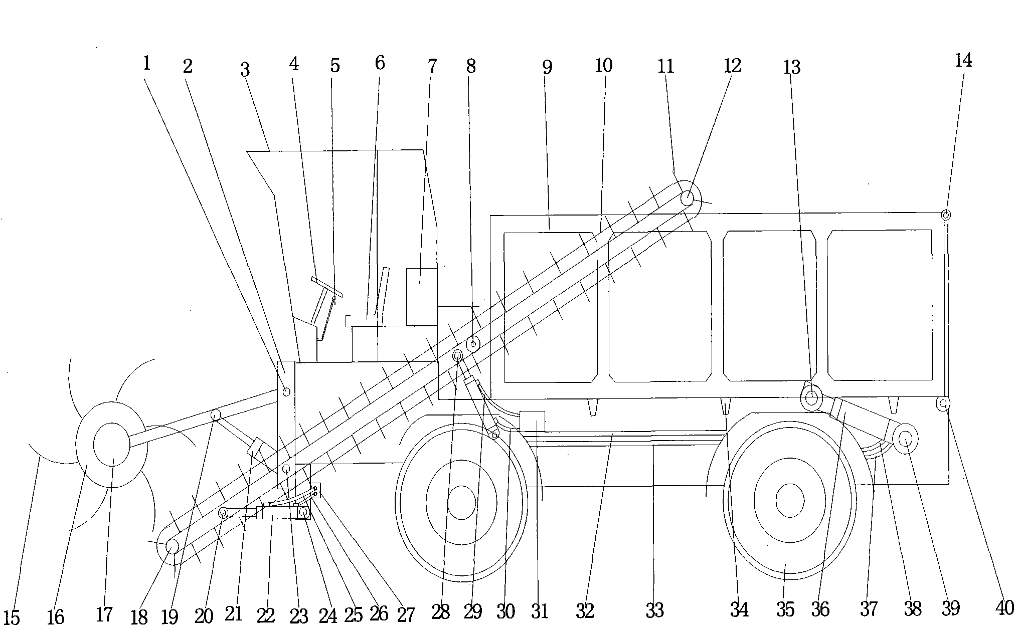
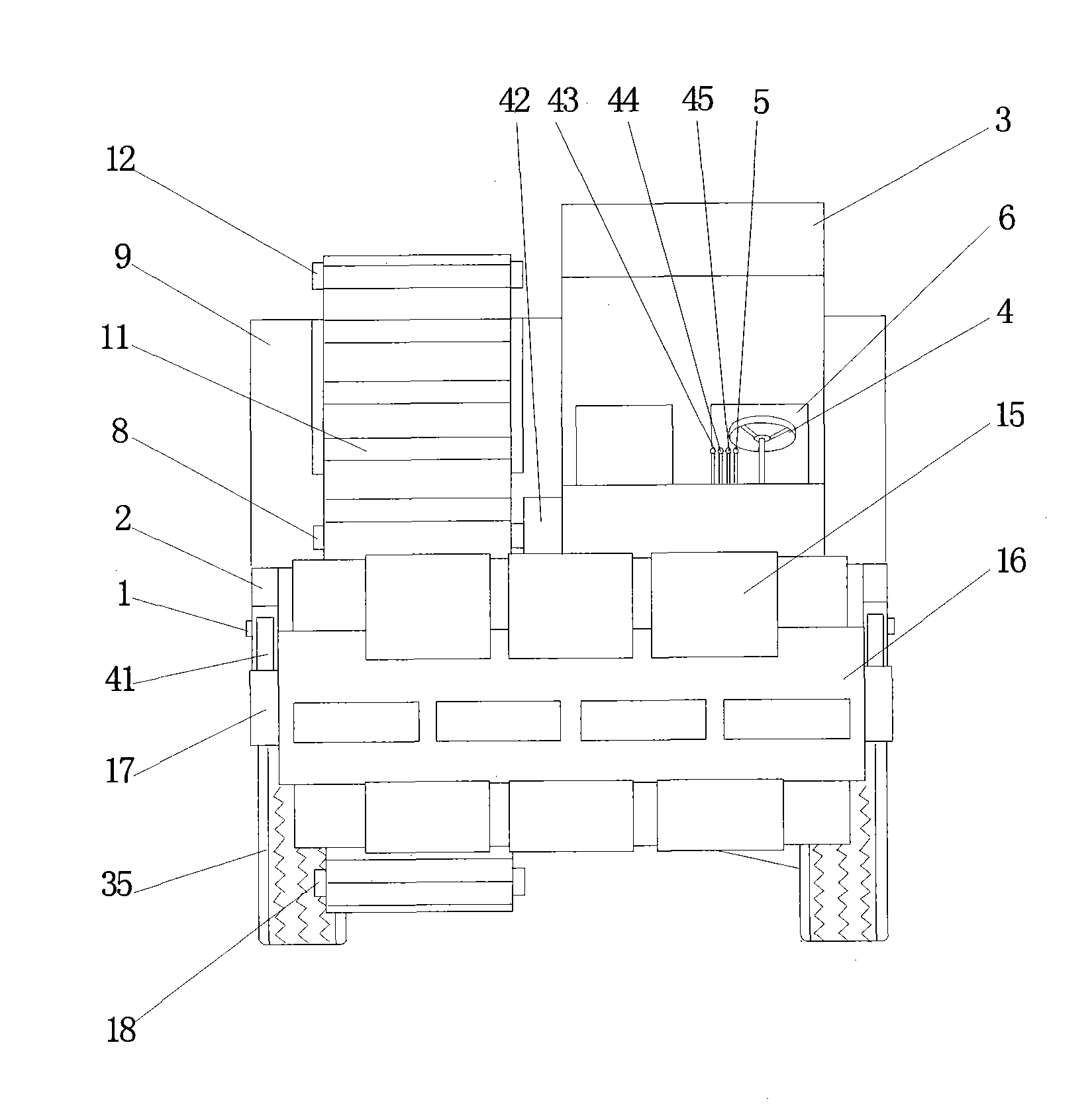
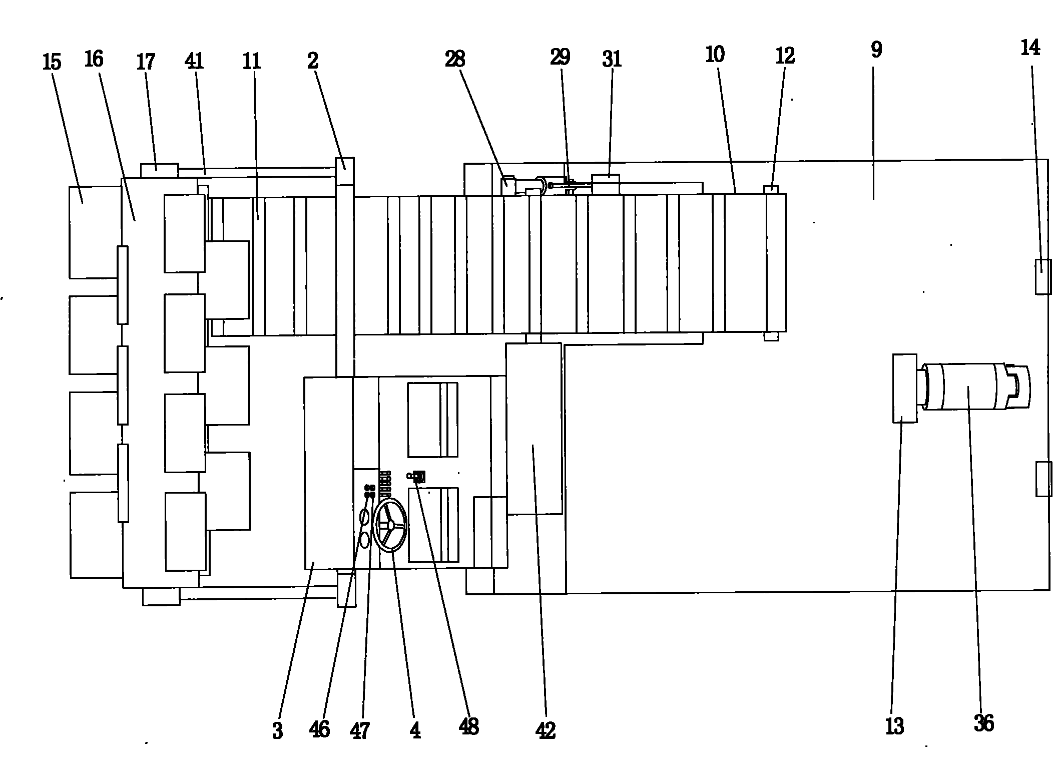
[0011] A moss removal machine, mainly composed of a cab, a scraper shaft, a hydraulic valve, a hydraulic cylinder, a conveyor belt, etc., is characterized in that the motor (17) connected to the frame (2) is fixed by a pin shaft (1) On the bracket (41), when the driver presses the switch (46), the motor (17) drives the scraper shaft (16) to rotate, and the scraper (15) mounted on the scraper shaft (16) rotates accordingly The moss is scraped to one end of the conveyor belt (10), and at the same time the driver presses the switch (47), and the motor (42) rotates to drive the drive shaft (8) connected thereto, and the drive shaft (8) rotates to drive the drive shaft (8) installed on the The passive shafts (12) and (18) at both ends of the conveyor belt (10) rotate, and at this time the conveyor plate (11) installed on the conveyor belt (10) also rotates at the same time, and the moss is sent into the conveyor belt by the scraper shaft (16). plate (11), and then conveyed to the c...


PUM


Abstract

The invention discloses a moss clearing conveyor, and relates to a clearing conveyor, in particular to a moss clearing conveyor used at the places such as river bank, seaside, lakeside and the like. The moss clearing conveyor solves the problems of low clearing speed and waste of manpower and material resources because relevant departments adopt manpower to fish moss floaters or loaders to clear moss floaters once beaches of all coastal cities are subjected to the intrusion of certain moss floaters and the moss floaters are transported out of the beaches by transportation vehicles in the background technology. In order to solve the problems of the background technology, the invention adopts the technical scheme that the moss clearing conveyor mainly comprises a cab, a scraper shaft, a hydraulic valve, a hydraulic cylinder, a conveyer belt and the like. The moss clearing conveyor has the advantages of convenient operation, high speed and thorough clearing, saves the manpower and the material resources, and provides an effective machine for replacing manpower work for the relevant departments and the certain coastal cities.

Description


Claims


Application Information

Patent Timeline
Owner 王丽瑛
Learn More