
Anti-theft lock core

A technology of anti-theft lock cylinders and cylinders, which is applied in construction locks, cylinder locks, locks with rotating keys, etc., can solve the problems of poor anti-theft performance, improve anti-theft performance, enhance safety, and prevent damage to locks core effect

Inactive Publication Date: 2010-10-06
胡连志
View PDF5 Cites 15 Cited by
  • Summary
  • Abstract
  • Description
  • Claims
  • Application Information

AI Technical Summary

Problems solved by technology

If this type of lock is subjected to vibration force and rotation force at the same time, it is very easy to unlock it with a master key.
In addition, special tools can also be used to dial the bullets one by one into the lock cylinder shell with certain skills, so that the lock cylinder can rotate to open the anti-theft lock, and the anti-theft performance is poor.

Method used


Image

  • Anti-theft lock core
  • Anti-theft lock core
  • Anti-theft lock core

Examples


Embodiment Construction

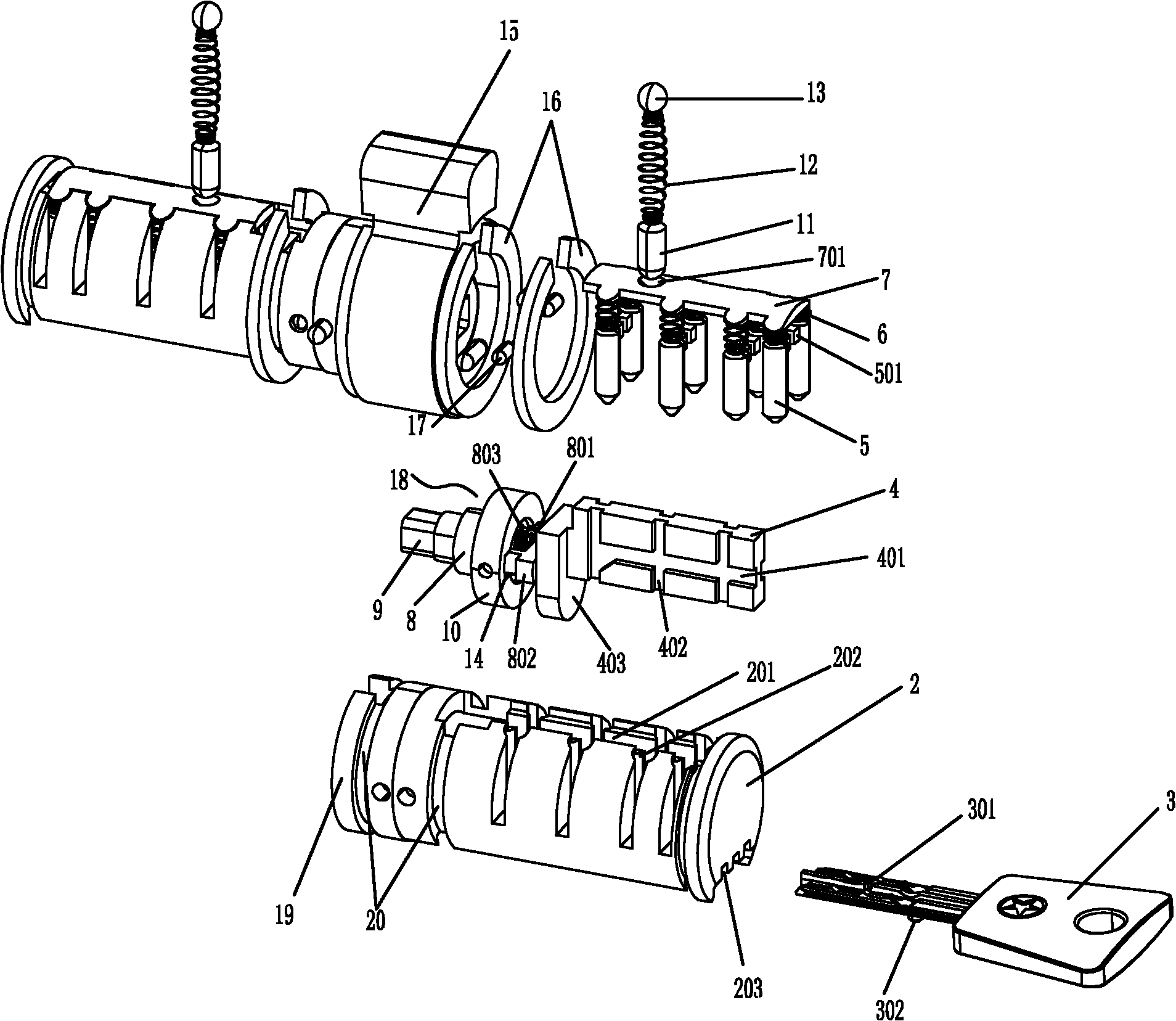
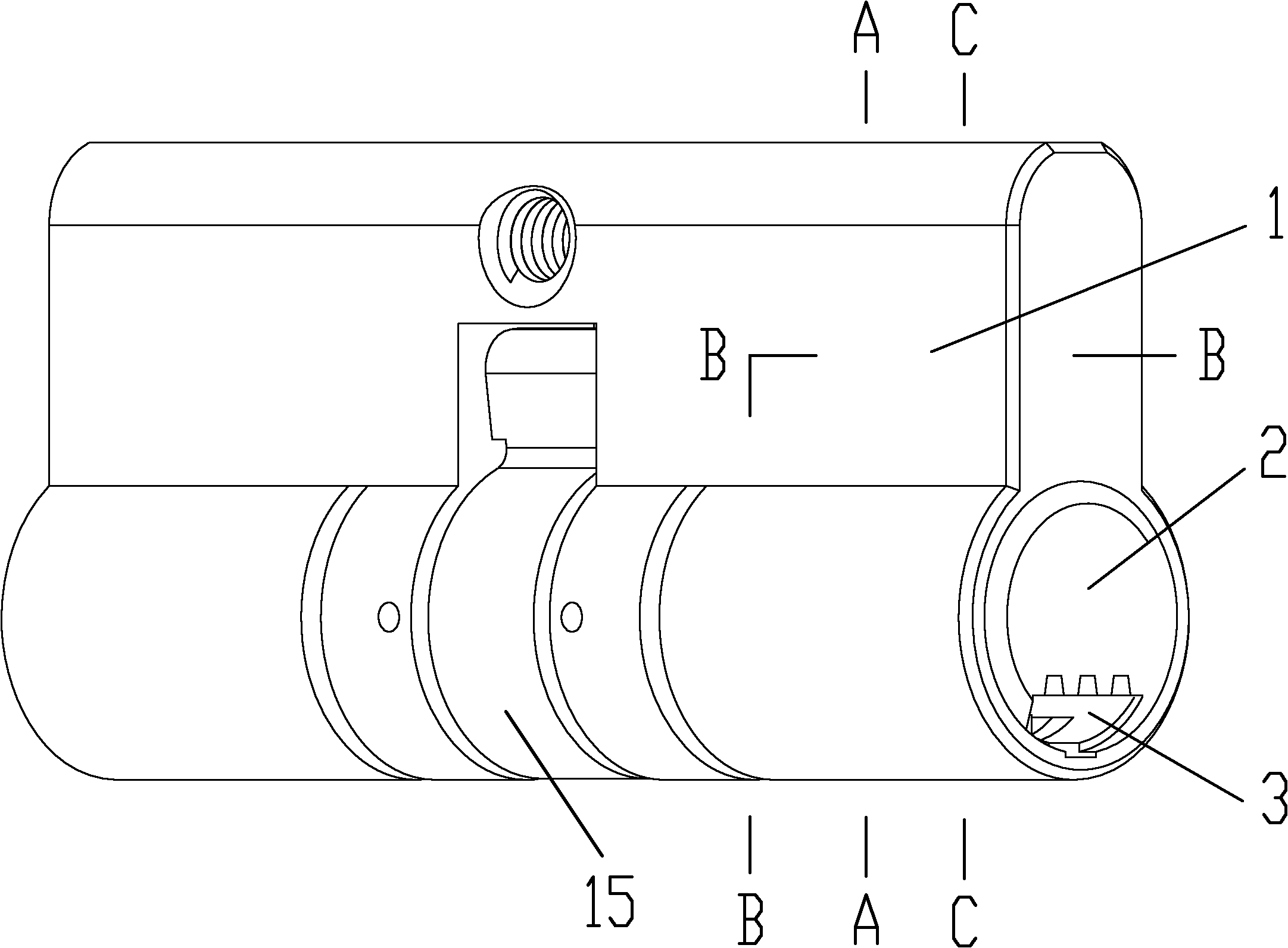
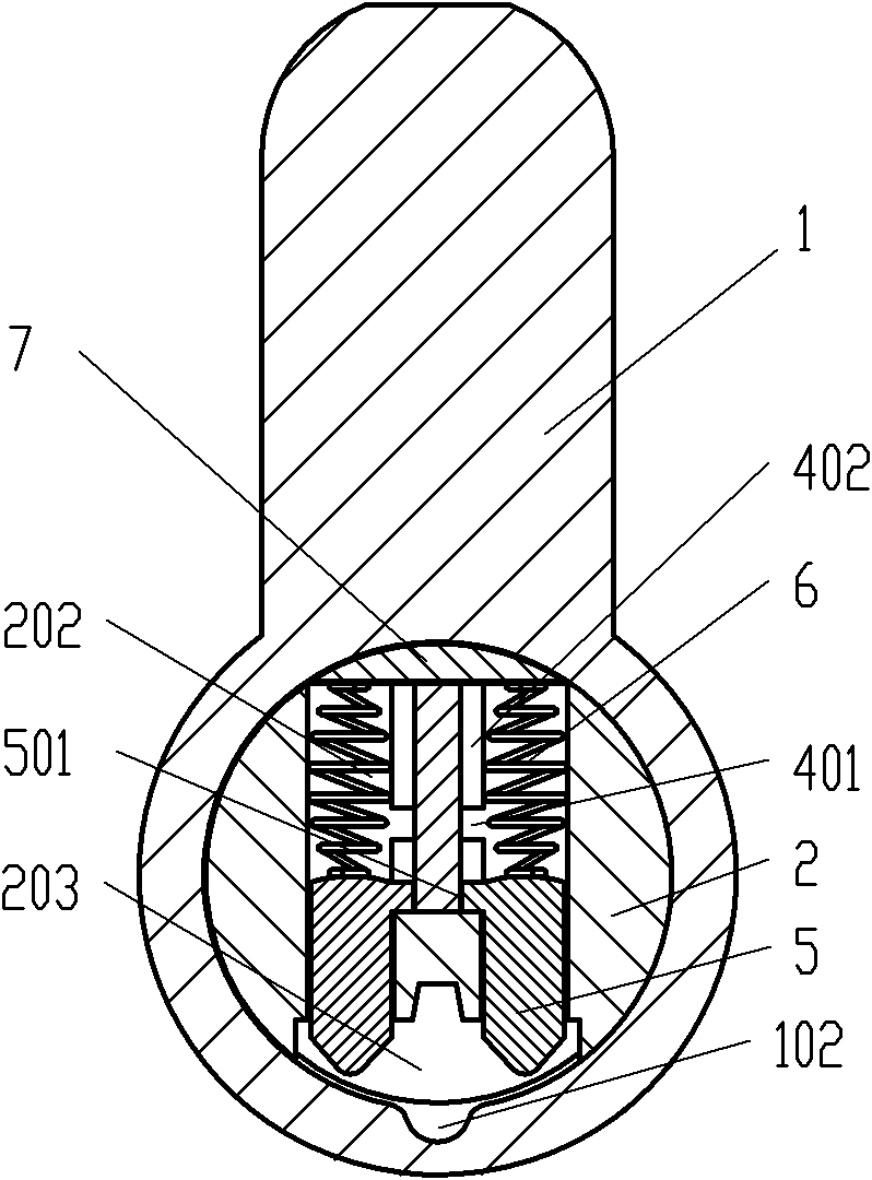
[0021] Such as figure 1 , figure 2 The shown anti-theft lock cylinder is mainly composed of a mandrel 9, a dial 15 installed in the center of the mandrel 9, a key 3, a lock cylinder shell 1 and a lock cylinder 2 with a key hole 203. To form left and right two rows of pinholes 202 that are symmetrical and communicate with the keyhole 203, each pinhole 202 is provided with a bullet post 5 and a pressing spring 6 from bottom to top. The top of the arc-shaped briquetting block 7 is set, and the briquetting block 7 is offset against the inner wall of the cylinder housing 1. A slider groove 201 is formed between the two groups of pinholes 202, and a slider 4 that can move axially along the lock cylinder 2 is installed in the slider groove 201, and the two side walls of the slider 4 are provided with holes that communicate with the pinholes 202. The longitudinal track groove 402 and the transverse track groove 401 , the upper part of the bullet 5 forms a bump 501 , and the bump 50...


PUM


Abstract

The invention relates to an anti-theft lock core. The existing anti-theft lock core only needs two steps to complete the unlocking process, thus, the anti-theft property is poor. The anti-theft lock core of the invention is characterized in that a plurality of spring holes which are arrayed in line and are communicated with a keyhole are formed in the lock lining along the axial direction thereof; the inside of each spring hole is provided with a spring pillar and a pressing spring from bottom to top; the upper part of each pressing spring is provided with an arc pressing block which is pressed against the inner wall of a lock lining shell; a sliding block groove is formed in the lock lining; a sliding block which can move axially along the lock lining is arranged in the sliding block groove; the sliding block is provided with a longitudinal track groove and a transverse track groove which are communicated with the spring holes; the spring pillars are provided with bumps; the bumps are positioned in the longitudinal track groove; a baffle plate extending downwards is formed at the inner end of the sliding block; and the baffle plate is pressed against a resettable moving component which is arranged on a core shaft and can rotate around the core shaft. The invention divides the unlocking process into three steps to complete and increases a function of moving forwards so as to effectively improve safety of the lock.

Description

technical field [0001] The invention belongs to a lock core of a mechanical lock, in particular to an anti-theft lock core. Background technique [0002] Existing mechanical lock cores mainly include a cylinder shell and an internal cylinder, pinholes are provided at the corresponding positions of the cylinder shell and the cylinder, and pin pins, compression springs and sealing beads ( Or sealing marbles), the pinholes of the lock cylinder are provided with bullets that are offset against the clamping pins. When the key is inserted, the key squeezes the pins and pins of the clip, forcing all the pins of the clip to just return to the pinholes of the lock cylinder shell, so that the lock cylinder is not stuck, so that the lock cylinder can be rotated to make the shift block on it Drive the lock tongue to expand and contract to realize unlocking. After the key is pulled out from the hole, the snap pins return to the lock cylinder under the action of the return spring to rea...

Claims


Application Information

Patent Timeline
Patent Type & Authority Applications(China)
IPC IPC(8): E05B27/10E05B15/00E05B35/00E05B19/00
Inventor 胡连志
Owner 胡连志
Learn More