Support fixed structure of spiral heat exchange tube

A technology of spiral heat exchange tube and fixed structure, which is applied in the direction of heat exchanger shell, heat exchange equipment, lighting and heating equipment, etc. The effect of small processing cycle, reduced interaction force, and improved compactness

Active Publication Date: 2010-10-06
TSINGHUA UNIV
View PDF7 Cites 16 Cited by
  • Summary
  • Abstract
  • Description
  • Claims
  • Application Information

AI Technical Summary

Problems solved by technology

[0005] The technical problem to be solved by the present invention is to solve the problems of difficult processing, complex installation process and long assembly cycle of existing hard supports, and provide a support and fixing structure that can be applied to any spiral tube heat exchanger or steam generator

Method used


Image

  • Support fixed structure of spiral heat exchange tube
  • Support fixed structure of spiral heat exchange tube
  • Support fixed structure of spiral heat exchange tube

Examples


Embodiment 1

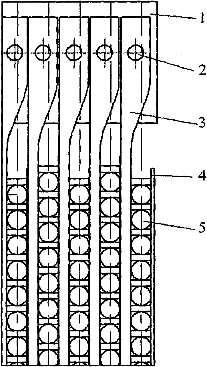
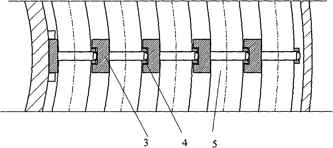
[0032] A sectional view of a supporting and fixing structure of a spiral heat exchange tube is shown in FIG. 1 . Figure 1a is a vertical section view, Figure 1b A cross-sectional view in the horizontal direction. The spiral heat exchange tubes 5 are arranged in the vertical direction, and the fixing and support of the spiral heat exchange tubes 5 in the vertical direction are completed by the locking teeth of the load-bearing bar 3 and the fixing bar 4 together. 5 Carry out the limit in the circumferential direction. The load-bearing strips 3 between different layers are independent from each other in the radial direction, so as to ensure that the spiral heat exchange tube 5 can expand freely in the radial direction when in a hot state. The spiral heat exchange tube 5 is tightly connected with the load-bearing bar 3 through the fixing bar 4 to prevent loosening during operation. The load-bearing bars 3 are connected with the suspension ribs 1 through the fixing pins 2 to r...

Embodiment 2

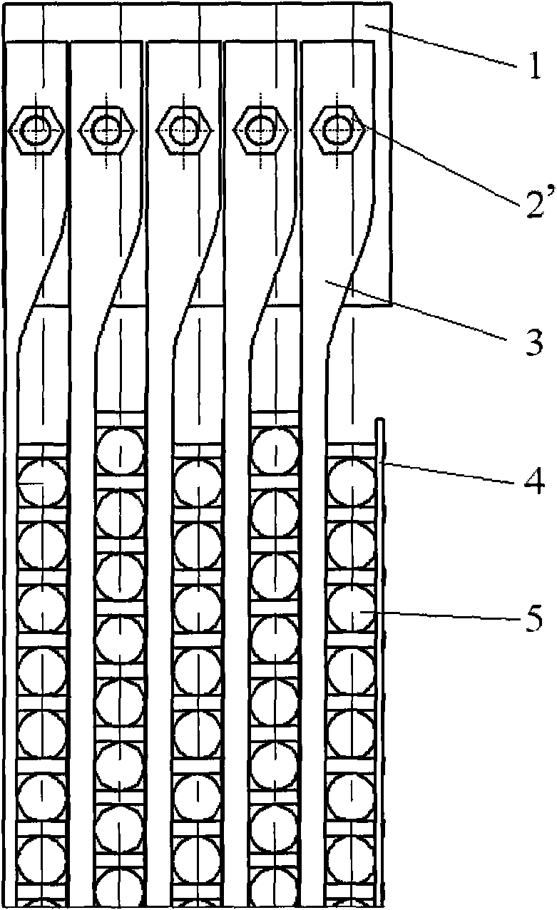
[0034] A cross-sectional view of a supporting and fixing structure of a spiral heat exchange tube connected by bolts is shown in figure 2 shown. This embodiment is similar to the support and fixing structure of the heat exchange tubes in Embodiment 1, and the difference from Embodiment 1 is that the connection between the load-bearing bar 3 and the suspension rib 1 in this embodiment is a bolt connection, so Said bolt is represented by 2'.

Embodiment 3

[0036] The load-bearing strips of the supporting and fixed structure of the spiral heat exchange tubes can be designed in a split type. For the structure of the load-bearing strips, see image 3 . This embodiment is similar to the support and fixing structure of the heat exchange tubes in the first embodiment, and the difference from the first embodiment is that the load-bearing bar is divided into two parts: the load-bearing bar A and the locking teeth B. The side of the carrying bar A close to the heat exchange tube is opened with shaped slots to fix the teeth B. There are protruding shoulders on both sides of the locking tooth B, which can be inserted into the slot from both ends of the carrier bar A, and when it slides to a suitable position (when the positions of the holes on B and the holes on A correspond to each other) ), using pins to fix, so that the locking teeth B and the carrier bar A are connected as a whole.

[0037] It can be seen from the above embodiments...


PUM


Abstract

The invention discloses a support fixed structure of a spiral heat exchange tube, comprising a suspended rib plate, a bearing strip and a fixed strip, wherein the suspended rib plate is located at the top end of a heat exchange tube bundle and is used for bearing the weight of all heat exchange tubes and fluid media in the heat exchange tubes; the bearing strip is connected with the suspended rib plate, is located at the inner side of the heat exchange tube and comprises a load bearing strip and a latch, and the back surface of the load bearing strip and the reverse side of the latch are provided with limit grooves in which the latch of the bearing strip at an inner ring and the fixed strip are clamped; and the fixed strip is located on the outer side of the heat exchange tube and is provided with a hole at the position corresponding to the latch of the bearing strip so as to enable the end socket of the latch to penetrate through and be fixed with the fixed strip. The support fixed structure of the invention can solves the problems of high process difficulty, complex installation process and long assembly period of the existing hard support.

Description

technical field [0001] The invention relates to the technical field of thermal engineering, in particular to a supporting and fixing structure of a spiral heat exchange tube. Background technique [0002] For spiral tube heat exchange tubes or steam generators, most of the world currently use hard support structures, such as the support structure of the heat exchange tubes of the German THTR thorium high temperature gas-cooled reactor steam generator and the HTR-MODULE high temperature gas-cooled reactor steam generator Support structure for heat exchange tubes. The heat transfer tube bundle is fixed on the support plate through a fixed structure. The fixed structure of the heat exchange tube bundle is double-layered, and the inner layer is two semicircular casings, and the outer surface of the casing has a certain taper. The outer structure is a complete sleeve, and the inner surface of the sleeve has a certain taper. The inner and outer tubes are fastened to each other, ...

Claims


Application Information

Patent Timeline
Patent Type & Authority Applications(China)
IPC IPC(8): F28F9/013
Inventor 雒晓卫李笑天何树延吴莘馨王洪涛
Owner TSINGHUA UNIV
Why Eureka
Try Eureka