
Welding and cutting machine

A welding and cutting machine and air compressor technology, applied in welding equipment, plasma welding equipment, metal processing equipment, etc., can solve the problems of low integration and cluttered layout of welding and cutting machines, improve integration, optimize wiring layout, The effect of reducing the floor space

Pending Publication Date: 2021-01-29
上海气焊机厂有限公司
View PDF0 Cites 1 Cited by
  • Summary
  • Abstract
  • Description
  • Claims
  • Application Information

AI Technical Summary

Problems solved by technology

[0005] The object of the present invention is to provide a welding and cutting machine to solve the problems of messy internal layout and low integration of the welding and cutting machine

Method used


Image

  • Welding and cutting machine
  • Welding and cutting machine
  • Welding and cutting machine

Examples


Embodiment Construction

[0030] In order to make the technical problems solved by the present invention, the technical solutions adopted and the technical effects achieved clearer, the technical solutions of the present invention will be further described below in conjunction with the accompanying drawings and through specific implementation methods. It should be understood that the specific embodiments described here are only used to explain the present invention, but not to limit the present invention. In addition, it should be noted that, for the convenience of description, only the parts related to the present invention are shown in the drawings but not all of them.

[0031] In the description of the present invention, unless otherwise clearly specified and limited, the terms "connected", "connected" and "fixed" should be understood in a broad sense, for example, it can be a fixed connection, a detachable connection, or an integrated ; It can be a mechanical connection or an electrical connection;...


PUM


Abstract

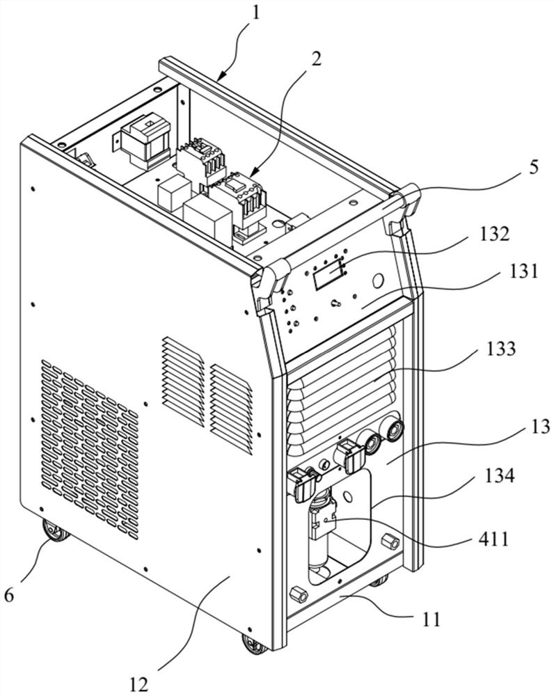
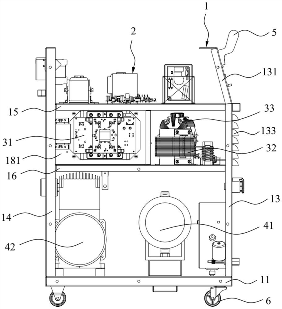
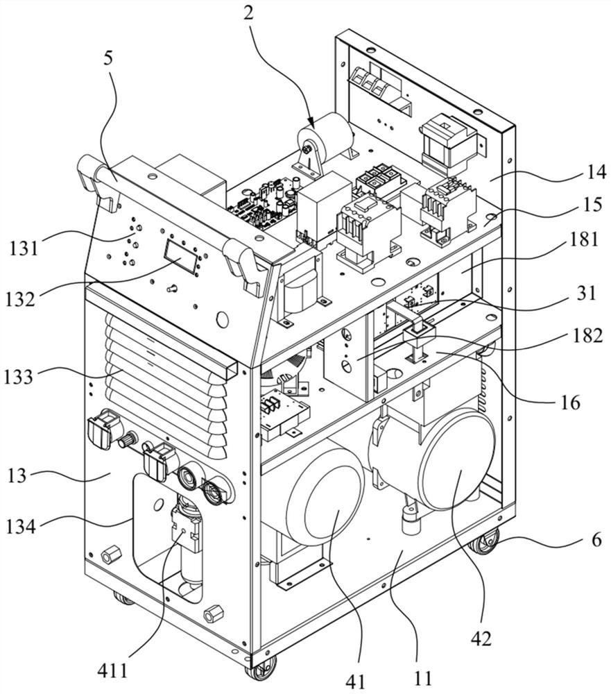
The invention relates to the technical field of welding machines, and discloses a welding and cutting machine. The welding and cutting machine comprises a shell, a first partition plate, a second partition plate, a control assembly part, a power supply assembly and an air supply assembly. The shell comprises a bottom plate, two side plates, a front plate and a rear plate, the front plate and the rear plate are oppositely arranged on the bottom plate, the two side plates are oppositely arranged on the bottom plate, and the two side plates, the front plate and the rear plate are connected and jointly define the shell with the bottom plate. The first partition plate and the second partition plate are arranged in the shell in a spaced mode and divide the shell into a first containing cavity, asecond containing cavity and a third containing cavity which are sequentially and adjacently arranged in the vertical direction from top to bottom, a control assembly is installed in the first containing cavity, a power supply assembly is installed in the second containing cavity, and the air supply assembly is installed in the third containing cavity. The shell of the welding and cutting machineis divided into the first containing cavity, the second containing cavity and the third containing cavity through the first partition plate and the second partition plate, and layered installation ofcomponents of the welding and cutting machine is achieved; and meanwhile, the welding and cutting machine is integrated with the air supply assembly, and the occupied area is reduced.

Description

technical field [0001] The invention relates to the technical field of welding machines, in particular to a welding and cutting machine. Background technique [0002] Existing plasma welding and cutting machines use compressed air as the working gas, and use the high-temperature, high-speed plasma arc as the heat source to locally melt the cut metal to form a narrow slit or weld two metal parts together. The equipment can cut or weld stainless steel, aluminum, copper and other metal materials. [0003] Due to the messy layout of the control components and power supply components inside the existing welding and cutting machine, the internal wiring is unreasonable, resulting in low utilization of the internal space of the welding and cutting machine, which is not conducive to the convenient operation and heat dissipation of the welding and cutting machine. Moreover, the welding and cutting machine has a low integration level and needs an external air compressor and gas storag...

Claims


Application Information

Patent Timeline
Patent Type & Authority Applications(China)
IPC IPC(8): B23K10/00
CPCB23K10/00
Inventor 不公告发明人
Owner 上海气焊机厂有限公司
Learn More