Support fixed structure of spiral heat exchange tube
A technology of spiral heat exchange tube and fixed structure, applied in the direction of heat exchanger shell, heat exchange equipment, lighting and heating equipment, etc., can solve the problems of complex installation process, difficult processing of hard bracing, long assembly cycle, etc., to achieve The effect of reducing the processing cycle, reducing the interaction force, and improving compactness
- Summary
- Abstract
- Description
- Claims
- Application Information
AI Technical Summary
Problems solved by technology
Method used
Image
Examples
Embodiment 1
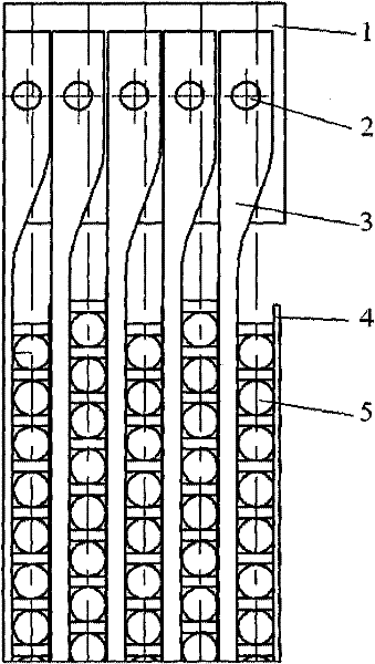
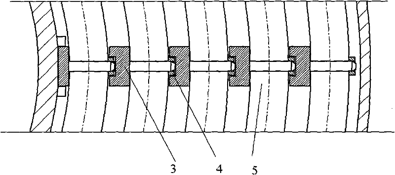
[0032] A sectional view of a supporting and fixing structure of a spiral heat exchange tube is shown in FIG. 1 . Figure 1a is a vertical section view, Figure 1b A cross-sectional view in the horizontal direction. The spiral heat exchange tubes 5 are arranged in the vertical direction, and the fixing and support of the spiral heat exchange tubes 5 in the vertical direction are completed by the locking teeth of the load-bearing bar 3 and the fixing bar 4 together. 5 Carry out the limit in the circumferential direction. The load-bearing strips 3 between different layers are independent from each other in the radial direction, so as to ensure that the spiral heat exchange tube 5 can expand freely in the radial direction when in a hot state. The spiral heat exchange tube 5 is tightly connected with the load-bearing bar 3 through the fixing bar 4 to prevent loosening during operation. The load-bearing bars 3 are connected with the suspension ribs 1 through the fixing pins 2 to r...
Embodiment 2
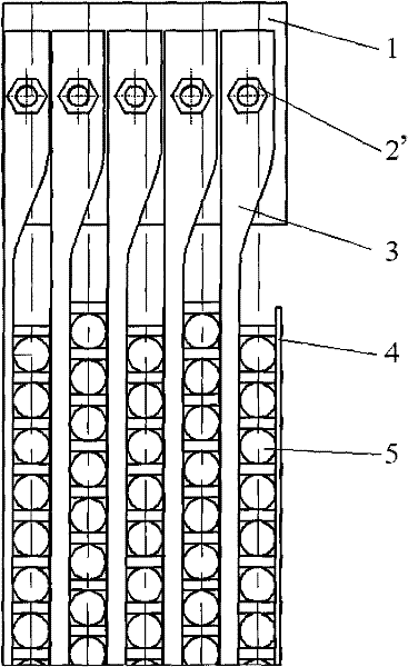
[0034] A cross-sectional view of a supporting and fixing structure of a spiral heat exchange tube connected by bolts is shown in figure 2 shown. This embodiment is similar to the support and fixing structure of the heat exchange tubes in Embodiment 1, and the difference from Embodiment 1 is that the connection between the load-bearing bar 3 and the suspension rib 1 in this embodiment is a bolt connection, so Said bolt is represented by 2'.
Embodiment 3
[0036] The load-bearing strips of the supporting and fixed structure of the spiral heat exchange tubes can be designed in a split type. For the structure of the load-bearing strips, see image 3 . This embodiment is similar to the support and fixing structure of the heat exchange tubes in the first embodiment, and the difference from the first embodiment is that the load-bearing bar is divided into two parts: the load-bearing bar A and the locking teeth B. The side of the carrying bar A close to the heat exchange tube is opened with shaped groove to fix the latch B. There are protruding shoulders on both sides of the locking tooth B, which can be inserted into the slot from both ends of the carrier bar A, and when it slides to a suitable position (when the positions of the holes on B and the holes on A correspond to each other) ), using pins to fix, so that the locking teeth B and the carrier bar A are connected as a whole.
[0037] It can be seen from the above embodiment...
PUM
 Abstract
Description
Claims
Application Information
 - R&D
- Intellectual Property
- Life Sciences
- Materials
- Tech Scout
- Unparalleled Data Quality
- Higher Quality Content
- 60% Fewer Hallucinations
Browse by: Latest US Patents, China's latest patents, Technical Efficacy Thesaurus, Application Domain, Technology Topic, Popular Technical Reports.
© 2025 PatSnap. All rights reserved.Legal|Privacy policy|Modern Slavery Act Transparency Statement|Sitemap|About US| Contact US: help@patsnap.com


