Target tracking method for wireless multimedia sensor network
A multimedia sensor and target tracking technology, applied in network topology, wireless communication, advanced technology, etc., can solve the problems of communication energy consumption, and achieve the effect of ensuring service life, extending network life, and saving energy
- Summary
- Abstract
- Description
- Claims
- Application Information
AI Technical Summary
Problems solved by technology
Method used
Image

Examples
Embodiment Construction
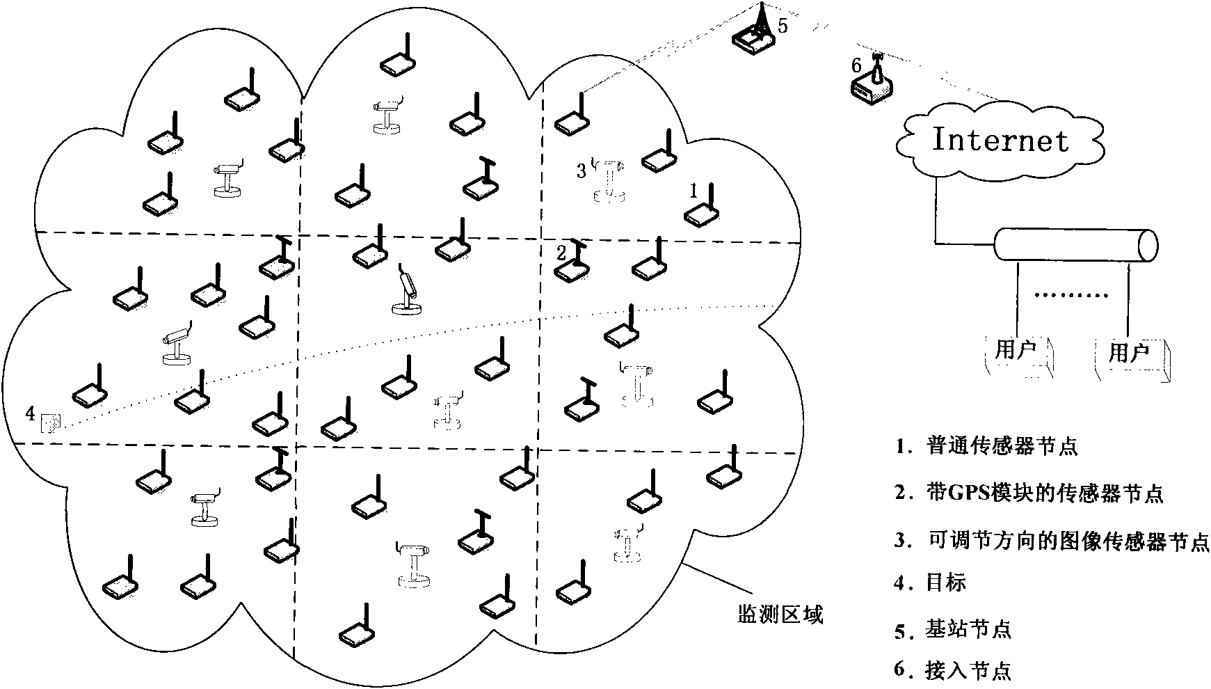
[0038] The invention adopts common sensor nodes, sensor nodes equipped with GPS modules and image sensor nodes with adjustable direction to cooperate with each other to complete target tracking. Each node in the network can play its own advantages, thereby saving costs and prolonging the life of the network, and can complete the tracking of the target in real time.
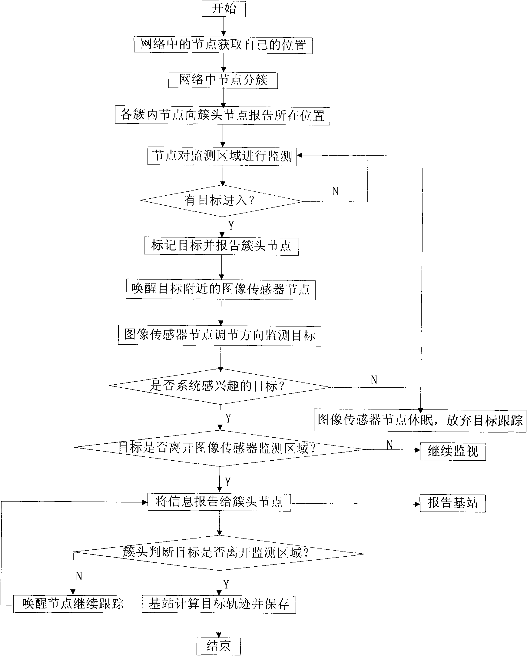
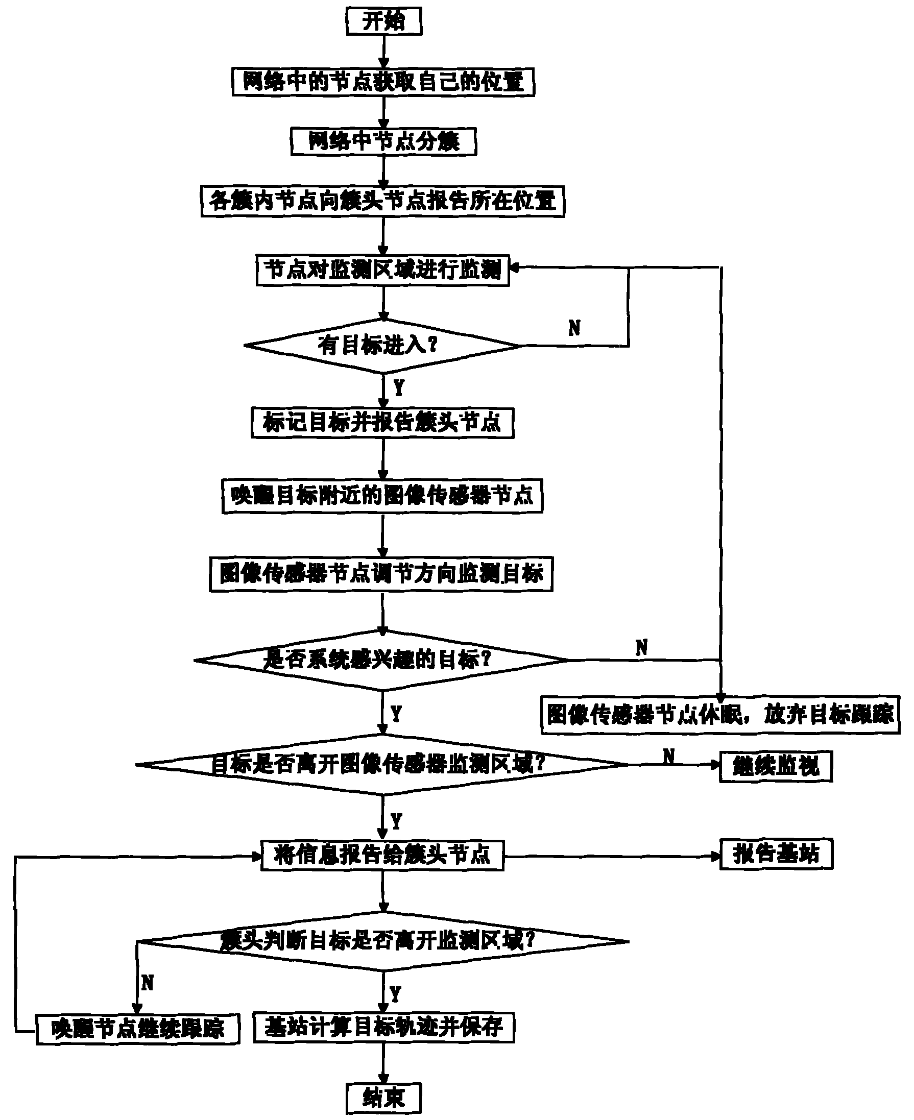
[0039] The target tracking method in the wireless multimedia sensor network that the present invention proposes has the following steps:
[0040] Step 1) Node types and their functions in the network. In the network, there are mainly three types of nodes: ordinary sensor nodes, sensor nodes equipped with GPS modules, and image sensor nodes with adjustable directions. The main functions of ordinary sensor nodes are abnormal detection, Target positioning and data transmission; the main function of the sensor node equipped with the GPS module is to obtain the position of the node itself and the function of the ordina...
PUM
 Abstract
Description
Claims
Application Information
PatSnap Eureka turns technology decisions into work you can execute. Powered by our Innovation Knowledge Graph, it runs expert workflows across engineering, life sciences, materials and intellectual property. Get your review-ready output in minutes.


