Method for fitting an equipping device

An assembly device and equipment technology, applied in the direction of electrical components, electrical components, etc., can solve problems such as deviations

Active Publication Date: 2010-10-06
ASM ASSEMBLY SYST GMBH & CO
View PDF3 Cites 6 Cited by
  • Summary
  • Abstract
  • Description
  • Claims
  • Application Information

AI Technical Summary

Problems solved by technology

However, the efficiency of the assembly device here depends on many boundary conditions, so that the value of the theoretical assembly efficiency partly deviates significantly from the real assembly efficiency

Method used


Image

  • Method for fitting an equipping device
  • Method for fitting an equipping device
  • Method for fitting an equipping device

Examples


Embodiment Construction

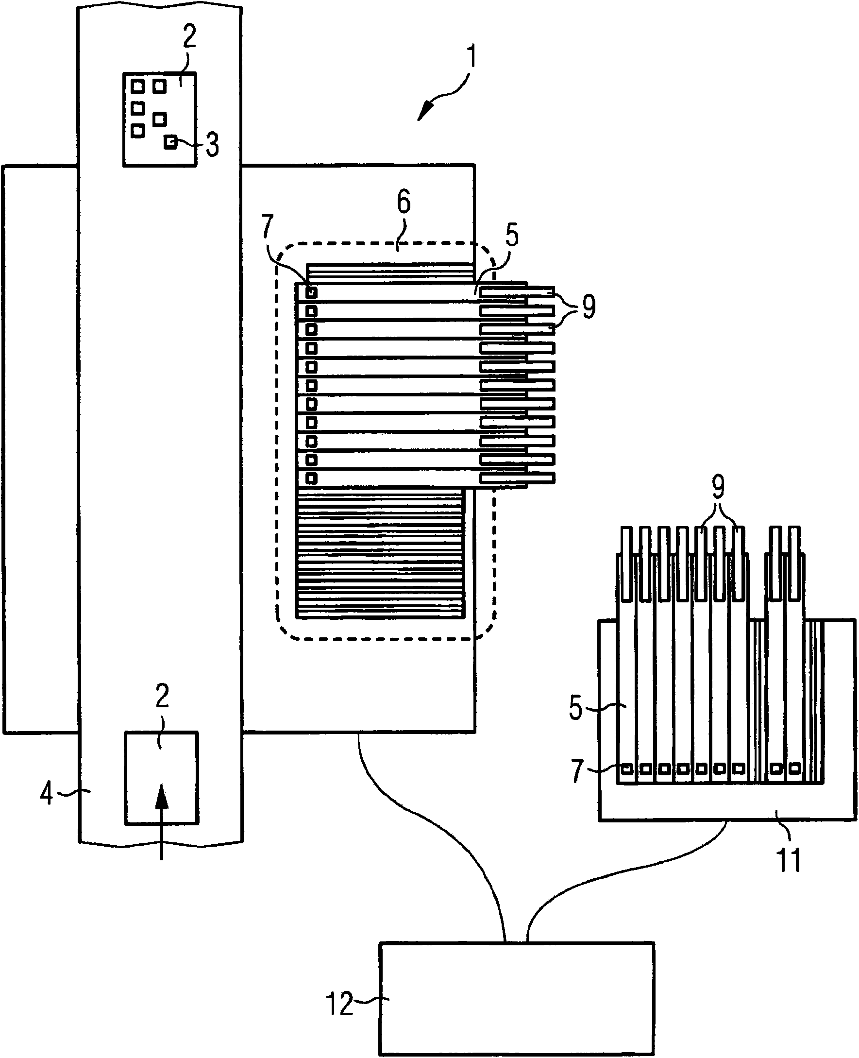
[0035] figure 1 A schematic plan view of the assembly device 1 is shown schematically, which in this embodiment is shown as a separate automatic assembly machine. However, it is also possible for the assembly device 1 to have a plurality of individual machines in a production line. The assembly device 1 is used for assembling components 3 on the substrate 2 . The substrate 2 is transported via the transport path 4 into the assembly area of ​​the assembly device 1 , where it is mounted with components 3 . Components 3 are supplied into a supply area 6 by means of a supply device 5 at a defined pick-up position 7 for picking. The picking up of the components 3 and the mounting of the substrate 2 can take place, for example, by means of a movable mounting head (not shown). The assembled substrate 2 is conveyed out of the assembly area of ​​the assembly device 1 through the conveying path 4 .

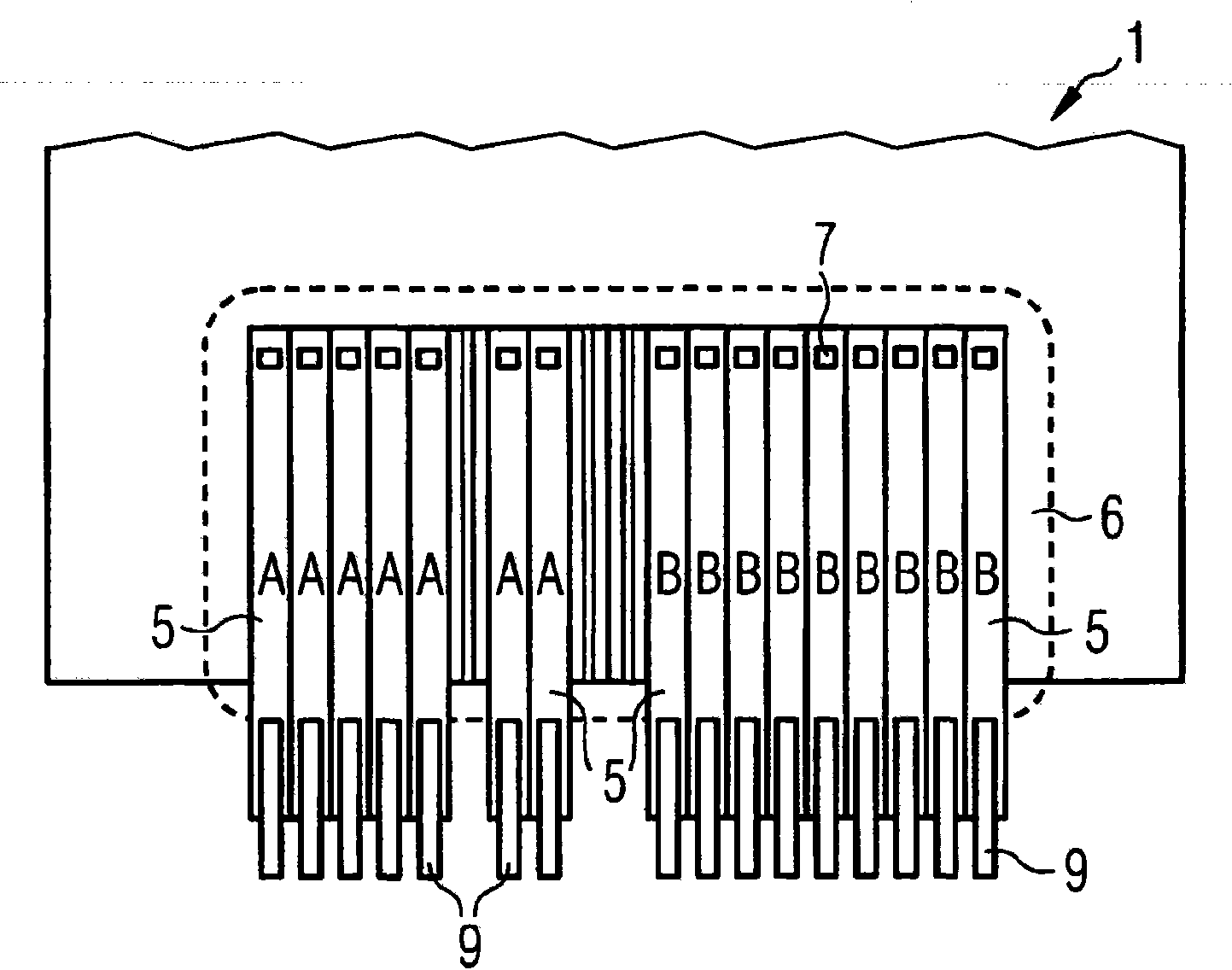
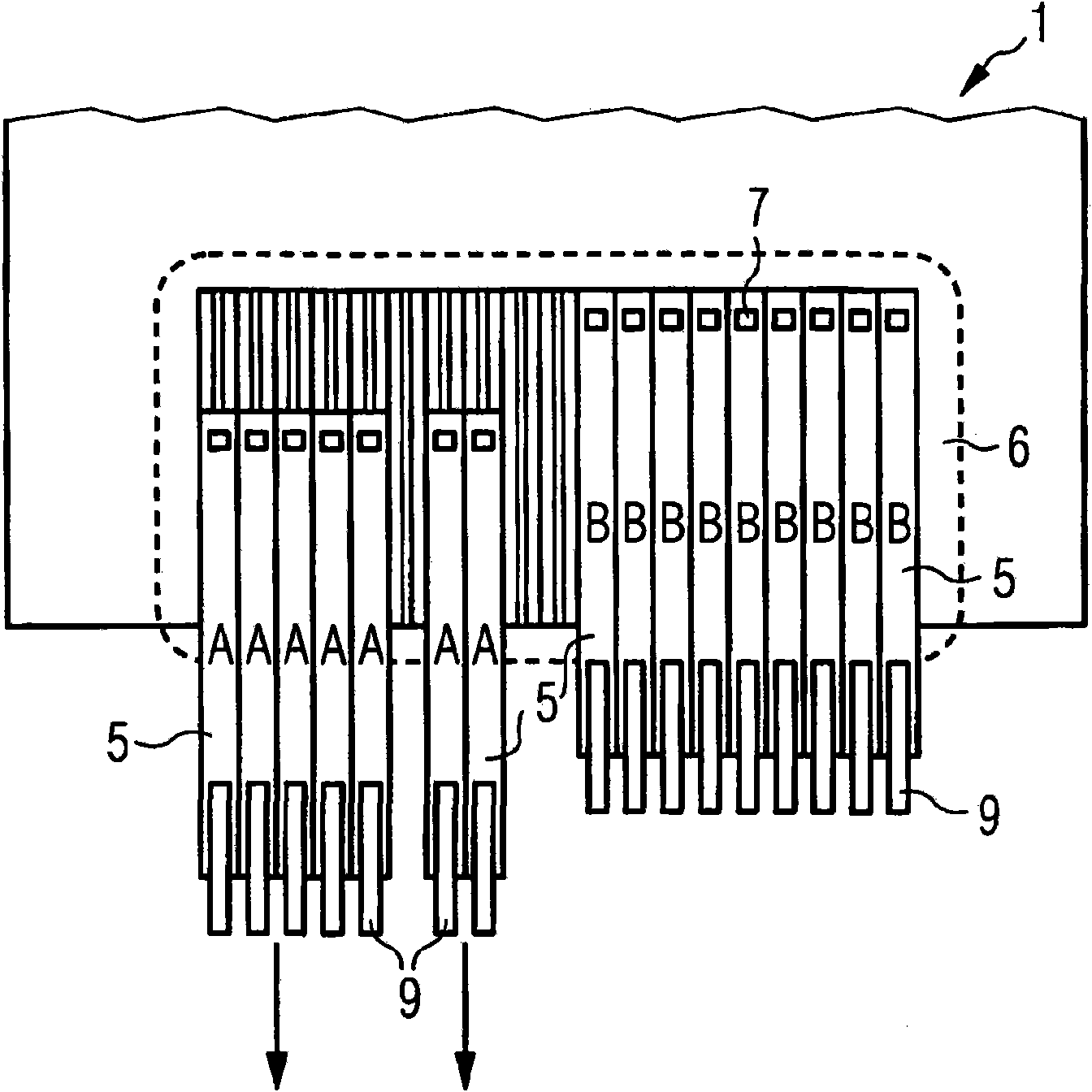
[0036] A defined number of supply devices 5 for different component types can be ar...


PUM


Abstract

The invention relates to a method for fitting an equipping device (1) with components (3) for machining production lots. A certain type of substrate (2) is equipped with components (3) for a production lot. Said method comprises the following steps: (a) the production lot to be machined is changed from type A to type B, and components (3) for machining type A and type B production lots are fitted on the equipping device (1), (b) the machining of the type B production lot is initiated, (c) components (3) required for machining the type A production lot are removed from the equipping device (1), during the machining of the type B production lot, and (d) the equipping device (1) is fitted with components (3) also required for machining a type C production lot. The type C production lot is machined after the type B production lot by means of the equipping device (1). The machinining of the type B production lot is continued during the fitting of the components (3). The fitting method is used to prevent, as far as possible, idle time caused by fitting time. The real equipping performance of the equipping device (1) can thereby be significantly increased.

Description

technical field [0001] The invention relates to the technical field of automatically assembling components on a component carrier by means of an assembly device. In particular, the invention relates to a method for equipping an assembly device with elements. Background technique [0002] In the mounting apparatus for mounting substrates with components, a supply device for supplying components is arranged on the side of a transport path for the substrates. The assembly head of the assembly device, which is movable by a positioning system, picks up the component from the supply device and moves it to the assembly area of ​​the assembly device, in which the substrate to be assembled is provided and the component is placed on this substrate. [0003] In this context, in recent years there has been a trend towards more efficient assembly devices which can process an increasing number of components per unit time. In this case, however, the efficiency of the assembly device depe...

Claims


Application Information

Patent Timeline
Patent Type & Authority Applications(China)
IPC IPC(8): H05K13/04
CPCH05K13/0417H05K13/0404H05K13/0452H05K13/0857H05K13/086
Inventor 罗伯特·胡贝尔
Owner ASM ASSEMBLY SYST GMBH & CO
Why Eureka
Try Eureka