Bias voltage control device of electrooptic modulator and control method thereof

An electro-optical modulator and bias voltage technology, which is applied in the direction of control/regulation systems, instruments, and adjustment of electrical variables, can solve problems such as difficult size, cost, not an independent system, and difficult implementation, so as to improve the extinction ratio and broaden the range. Application prospects, easy-to-achieve effects

Inactive Publication Date: 2012-09-05
NANJING FAAIBO OPTOELECTRONICS TECH
View PDF0 Cites 2 Cited by
  • Summary
  • Abstract
  • Description
  • Claims
  • Application Information

AI Technical Summary

Problems solved by technology

[0004] 1. The structure is complex, there are high requirements on the speed and precision of the components that make up the system, the cost is high, and it is difficult to realize
[0005] 2. It is not an independent system and requires the help of additional equipment (such as a PC), and is not easy to be used in instruments with limited volume and cost or other portable modular equipment;

Method used


Image

  • Bias voltage control device of electrooptic modulator and control method thereof
  • Bias voltage control device of electrooptic modulator and control method thereof
  • Bias voltage control device of electrooptic modulator and control method thereof

Examples


Embodiment Construction

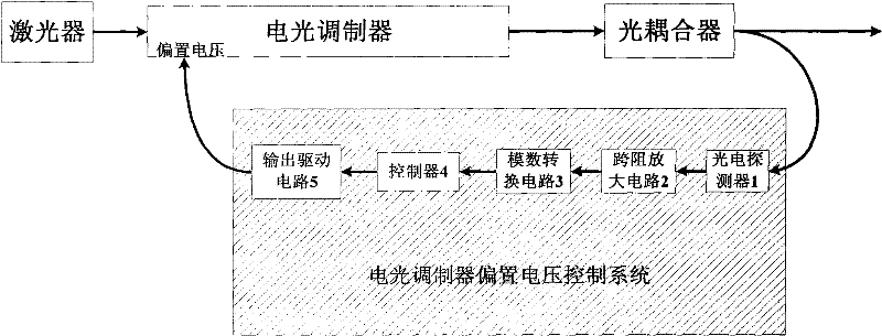
[0018] The device includes: a photodetector 1, a transimpedance amplifier circuit 2, an analog-to-digital conversion circuit 3, a controller 4, and an output drive circuit 5.

[0019] The photodetector part does not need high-speed devices, and the speed of the photodetector is tens of KHz to meet the requirements; the dark current of the photodetector should be as small as possible. When the driving voltage is 5V, the dark current should be less than 1nA, and the responsivity should be 0.5 A / W above. Only in this way can we ensure a good signal-to-noise ratio and ensure that the signal received by the controller is correct, so as to avoid misjudgment by the controller. The photodetector model used here is GD3560J, which is a near-infrared photodetector with a spectral sensitive band at 1550nm and a bandwidth of 400MHz; when the driving voltage is 5V, the maximum dark current of the photodetector is 1nA; the responsivity is 0.85 A / W, meeting the above requirements. Photodete...


PUM


Abstract

The invention discloses a bias voltage control device of an electrooptic modulator and a control method thereof. The bias voltage control device is a bias voltage drive developed aiming at the electrooptic modulator. By controlling bias voltage of the electrooptic modulator, the aim of ensuring that the electrooptic modulator stably works at a proper work place can be achieved. A photoelectric detector (1), a transimpedance amplifying circuit (2), an analogue-digital converting circuit (3), a controller (4) and an output drive circuit (5) of the bias voltage control device are connected in sequence; pulse light modulated by the electrooptic modulator splits out a part of light signals through an optical coupler to be connected with the input end of the photoelectric detector (1); and the output end of the output drive circuit (5) is connected with a bias voltage input port of the electrooptic modulator for controlling the bias voltage of the electrooptic modulator. The device realizesthe automatic control of the bias voltage of the electrooptic modulator, so that the electrooptic modulator continuously works at stable extinction ratio and the work stability of the electrooptic modulator can be improved.

Description

technical field [0001] The invention relates to a bias voltage driver of an electro-optic modulator, which is used for supplying a suitable bias voltage to the electro-optic modulator so that the electro-optic modulator works at a proper working point. It belongs to the field of automatic control. Background technique [0002] Electro-optic modulator is an optical device widely used in high-speed optical communication, optical fiber sensing and other fields. However, due to the structure of the electro-optic modulator, the operating point of the electro-optic modulator will slowly drift due to ambient temperature, mechanical distortion, mechanical vibration, and polarization state changes of the input light (shown in the view figure 2 ), resulting in a decrease in the extinction ratio of the electro-optic modulator and a deterioration in performance, which brings trouble to the application of the electro-optic modulator. Therefore, it is very necessary to automatically tra...

Claims


Application Information

Patent Timeline
Patent Type & Authority Patents(China)
IPC IPC(8): G05F1/10
Inventor 王顺张旭苹张凯张益昕路元刚
Owner NANJING FAAIBO OPTOELECTRONICS TECH
Why Eureka
Try Eureka