
Method and system for regulating an electrical converter for autonomous frequency stabilization with load transients in a micro-network comprising a diesel generating set

Active Publication Date: 2020-10-08
SOCOMEC
View PDF0 Cites 2 Cited by
  • Summary
  • Abstract
  • Description
  • Claims
  • Application Information

AI Technical Summary

Benefits of technology

The invention provides a system and method to maintain a stable operating point for the generating set during changes in load, reducing variations in frequency and voltage in the microgrid.

Problems solved by technology

However, control and protection are important issues in this type of network configuration.
When a PCS operates in parallel with a generating set, both operating as voltage generators, the interaction between the two control systems can sometimes cause instability of the voltage and frequency of the microgrid mainly during the load transient.
Particularly, by trying to follow the variations in frequency and voltage, the PCS will reduce or increase the load of the generating set which, upon seeing a load variation, will dynamically change the frequency of the generated electrical signal which may cause instability.
This causes a significant transient in the frequency and the voltage of the microgrid, even significantly disturbing the microgrid and the operating point of the generating set.
However, in this first aggregation, the microgrid is turned off when the generating set is switched off, because the PCS does not have the capacity to support the load and to stabilize the voltage and the frequency.
Unfortunately, in parallel operation, each load transient or variation of renewable energy will cause a voltage and frequency transient and a different operating point for the generating set.
However, any load variation will cause a frequency and voltage transient in the microgrid, due to the time response of the generating set control.
In addition, an instability could appear due to the interaction between the generating set and the PCS having the load transient as a trigger.
A known solution which attempts to use the EMS system to adapt the nominal PCS power during load transients, has intrinsic delays due to the time required to, firstly, measure the active power (which is not usually measured by the EMS but by an additional external peripheral device), secondly, calculate a new nominal power for the converter and, thirdly, transmit it to the converter itself (if there is more than one converter, this delay increases significantly).
These delays not only reduce the efficiency of this solution in frequency stabilization and in consumption of the group but can also affect the stability of the system because if the action of the converter is too delayed compared to the frequency variation event, an oscillatory behavior can be triggered.
Known systems fail to have a stable operating point for the generating set during the load transient, which unfortunately leads to a significant variation in frequency and voltage in the microgrid.
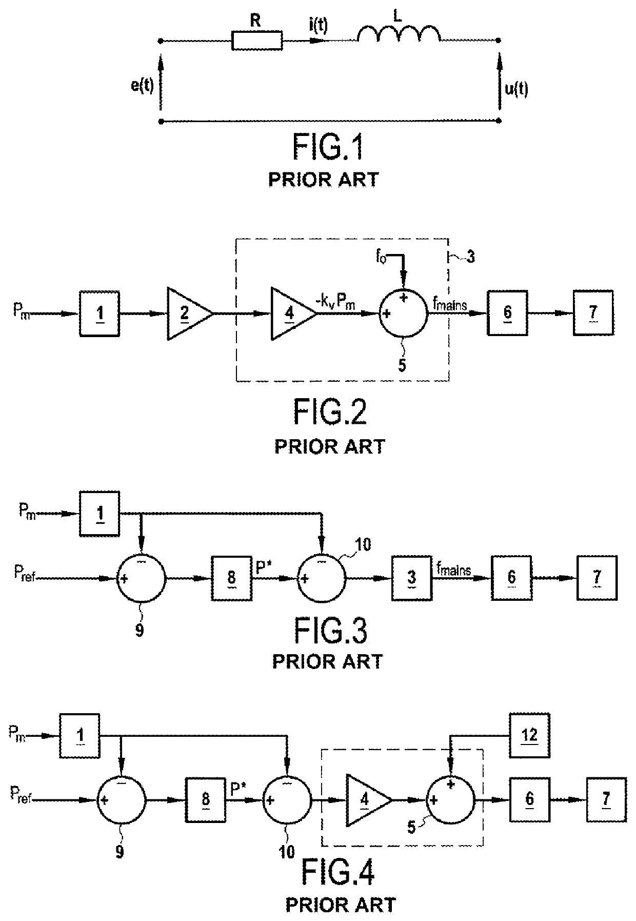
Under these conditions, the basic droop equations alone allow putting two or more sources in parallel but do not allow controlling the power exchanged between the converter and the mains, the converter being a PCS and the mains corresponding to a generating set for example.

Method used


Image

  • Method and system for regulating an electrical converter for autonomous frequency stabilization with load transients in a micro-network comprising a diesel generating set
  • Method and system for regulating an electrical converter for autonomous frequency stabilization with load transients in a micro-network comprising a diesel generating set
  • Method and system for regulating an electrical converter for autonomous frequency stabilization with load transients in a micro-network comprising a diesel generating set

Examples


first embodiment

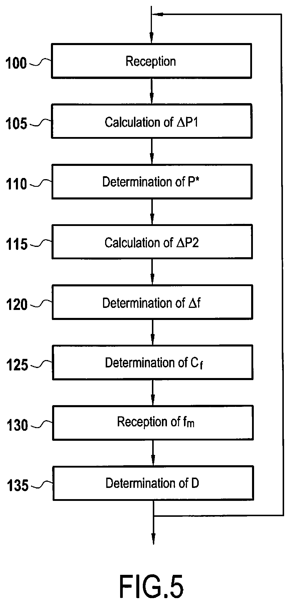
[0085]FIG. 5 schematically shows a flowchart of a method for regulating a converter, such as a power control system, for autonomously stabilizing the frequency in a microgrid to which the converter is intended to be connected, the microgrid comprising a generating set.

[0086]In this first embodiment of the regulation method, the method comprises a first step 100 of receiving an initial power setpoint Pref of the converter and an estimate of an active power Pm of the converter.

[0087]In a second step 105 of the regulation method, a first power variation ΔP1 is determined by calculating the difference between the initial power setpoint Pref and the estimated active power Pm.

[0088]In a third step 110 of the regulation method, a power regulation variable P* is determined from the first power variation ΔP1.

[0089]In a fourth step 115 of the regulation method, a second power variation ΔP2 is calculated from the difference between the power regulation variable P* and the estimated active powe...

second embodiment

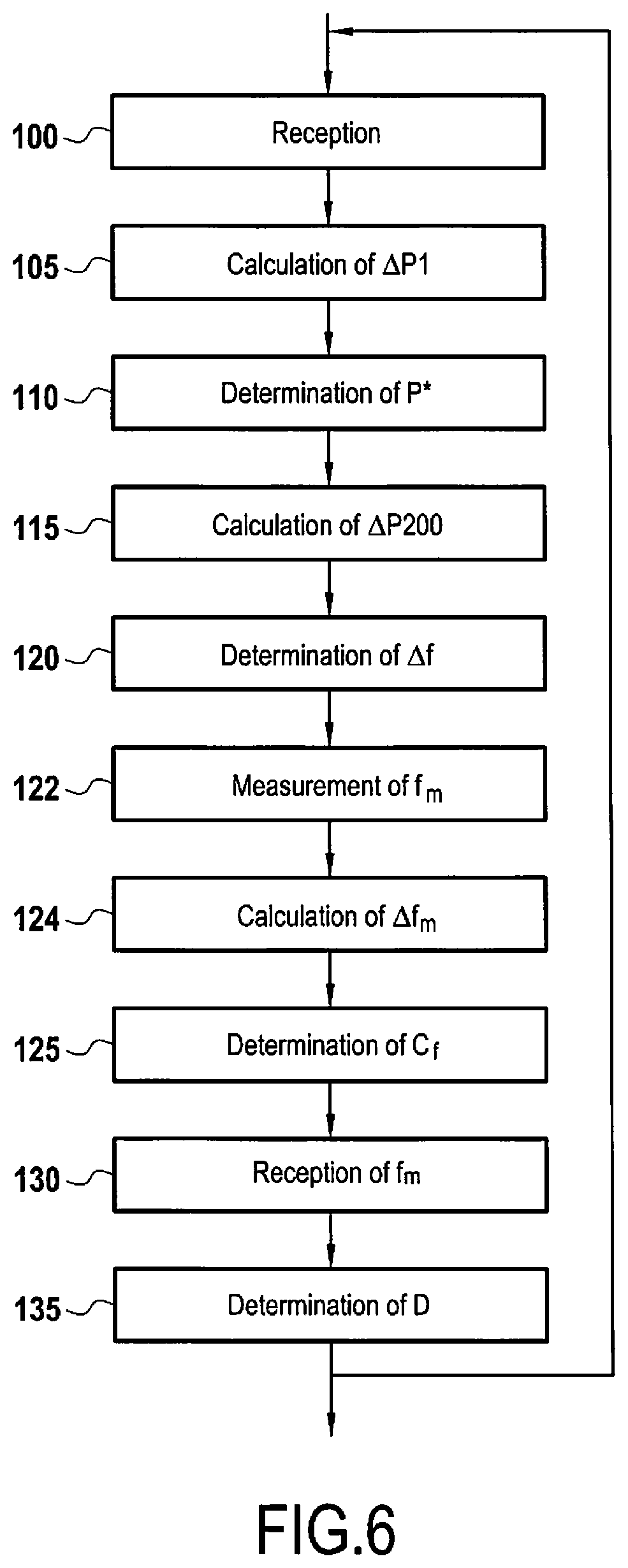
[0098]FIG. 6 shows a flowchart of a method for regulating a converter, such as a power control system, for autonomously stabilizing the frequency in a microgrid to which the converter is intended to be connected, the microgrid comprising a generating set.

[0099]The steps of the second embodiment of the regulation method illustrated in FIG. 6 identical to the steps of the first embodiment of the regulation method illustrated in FIG. 5 bear the same reference numerals.

[0100]The second embodiment of the regulation method illustrated in FIG. 6 differs from the first embodiment of the regulation method illustrated in FIG. 5 in that:[0101]it comprises a first additional step 122 in which the network frequency of the microgrid fm is measured with a phase-locked loop,[0102]it also comprises a second additional step 124 in which a difference Δfm between said measurement of the network frequency fm and a nominal frequency f0 of the converter, is calculated,[0103]the measured network frequency ...


PUM


Abstract

A method for regulating a converter to autonomously stabilize the frequency of a microgrid comprising a generating set, the method comprising: a determination of a power regulation variable from a power variation resulting from the initial power setpoint from which the estimated active power and the active damping value have been subtracted, a calculation of a second power variation at least from the difference between the power regulation variable and the estimated active power, and a determination of a frequency command value for commanding the converter from the second power variation, a reception of a frequency value characteristic of a load variation of said microgrid to which the converter is intended to be connected, and a determination of an active damping value from the received frequency value.

Description

BACKGROUND OF THE INVENTION[0001]The invention relates to a system and method for stabilizing the frequency in a microgrid comprising a generating set.[0002]The invention is applicable to microgrids or similar electrical installations in which a power converter, called “power converter system” (PCS) and normally using a battery such as an energy reservoir, works in parallel with a generating set forming an electrical production unit. The electrical production unit, that is to say the generating set, power supplies electrical loads and manages the distribution of electrical energy according to the difference between the electricity demands of the loads and the produced amount of electricity.[0003]A microgrid is a localized grouping of electricity sources and loads which operates normally connected and synchronous with the conventional centralized electrical network, also called “macrogrid”, but which can be disconnected and operate autonomously according to physical and / or economic c...

Claims


Application Information

Patent Timeline
IPC IPC(8): H02J3/38H02J13/00
CPCH02J2300/10H02J13/00002H02J3/381H02J3/46H02J2310/10Y02E40/70Y04S10/12Y02P80/14H02J3/241
Inventor CORRADIN, MICHELETOIGO, IGINOMATTAVELLI, PAOLO
Owner SOCOMEC
Learn More