
Prime motor output torque balance control system

A technology of balanced control and output torque, which is applied in the direction of engine control, machine/engine, mechanical equipment, etc., can solve the problems of small application range, complex structure and high cost of output torque adjustment technology, and achieve wide application range, simple structure and high performance reliable effect

Inactive Publication Date: 2008-11-12
ZHEJIANG UNIV OF TECH
View PDF5 Cites 3 Cited by
  • Summary
  • Abstract
  • Description
  • Claims
  • Application Information

AI Technical Summary

Problems solved by technology

[0005] In order to overcome the shortcomings of the existing prime mover or internal combustion engine output torque adjustment technology, such as complex structure, high cost and small application range, the present invention provides a prime mover output torque with simple structure, reliable performance, low cost and wide application range. Adjust the system to achieve a balanced control of its output torque

Method used


Image

  • Prime motor output torque balance control system
  • Prime motor output torque balance control system
  • Prime motor output torque balance control system

Examples


Embodiment 1

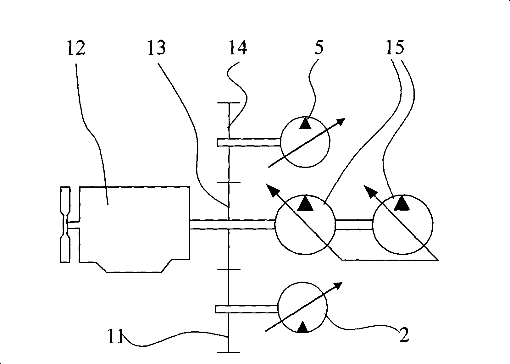
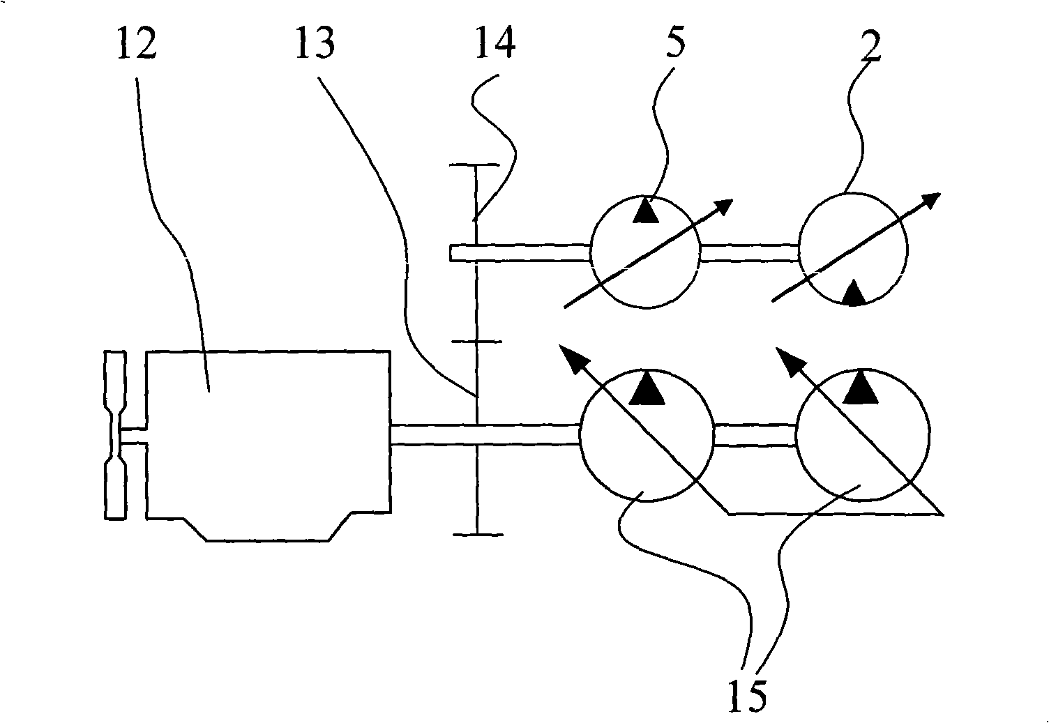
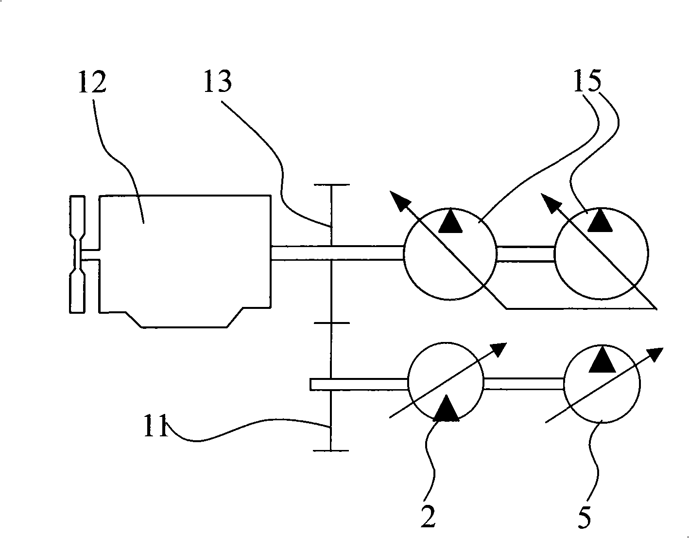
[0045] refer to figure 1 , Figure 14 , a prime mover output torque balance control system, the control system includes an energy storage pump 5, an accumulator 4, a power booster motor 2, transfer gears 11, 14 and a central gear 13 connected to the output shaft of an internal combustion engine 12, the energy storage The input shaft of the pump 5 is connected to the first transfer gear 14, the first transfer gear 14 meshes with the sun gear 13, the sun gear 13 is connected to the input shaft 15 of the main hydraulic pump, and the output shaft of the booster motor 2 is connected to the second Two transfer gears 11, the second transfer gear 11 meshes with the sun gear 13, the energy storage pump 5 is connected to the booster motor 2; the outlet of the energy storage pump 5 is connected to the The inlet and outlet of the accumulator 4, the first one-way valve 3 only allows hydraulic oil to flow from the outlet of the accumulator pump 5 to the inlet and outlet of the accumulator ...

Embodiment 2

[0059] refer to Figure 1-13 , Figure 15 , Figure 16 In this embodiment, the inlet and outlet of the accumulator 4 are connected to the inlet of the booster motor 2 through the second controlled one-way valve 9, and the controlled one-way valve 9 prevents hydraulic oil from flowing from the accumulator 4 without a control signal. The entrance and exit to the entrance of the booster motor 2; the torque controller outputs the signal P according to the pilot pressure of the construction machinery i , when the pilot pressure signal is greater than the preset threshold value, a channel command signal P is sent to the second controlled one-way valve 9 i . , the accumulator 4 is equipped with a pressure sensor 6, the outlet of the accumulator pump 5 is also connected to the oil tank 8 through the first controlled one-way valve 10, and the controlled one-way valve 10 is under the condition of no control signal Prevent hydraulic oil from the outlet of the accumulator pump 5 to th...


PUM


Abstract

The invention discloses a prime mover output torque equilibrium control system which comprises a hydraulic oil tank, an accumulator, a storage pump transmission connected with an output shaft of the prime mover and a power-steering motor, wherein, the output shaft of the prime mover is transmission connected with the output shaft of a main hydraulic pump; an exit of the storage pump is connected with an opening of the accumulator by a first one-way valve which allows the hydraulic oil to pass through the exit of the storage pump to the opening of the accumulator; the opening of the accumulator is connected with an entrance of the power-steering motor; the entrance of the power-steering motor is connected with the hydraulic oil tank by a second one-way valve which allows the hydraulic oil to enter the entrance of the power-steering motor from the oil tank; and the control system also comprises a torque controller which controls the storage pump and the discharge of the power-steering motor. The invention provides the prime mover output torque regulating system with simple structure, reliable performance, reduced cost and wide application range, which realizes the equilibrium control of the output torque.

Description

(1) Technical field [0001] The invention relates to the fields of fluid transmission control and prime mover torque control, and is suitable for various prime movers with severe load changes, especially the output torque balance control system of internal combustion engines and other prime movers in engineering machinery with severe load changes. (2) Background technology [0002] During the construction process of some construction machinery, due to the drastic change of the load, the output torque of the prime mover also changes greatly. For example, during the working process of a hydraulic excavator, its workload changes drastically, resulting in drastic changes in the working pressure of its hydraulic system, and because the hydraulic pump is directly driven by the diesel engine, the torque acting on the output shaft of the diesel engine also changes greatly , when the system pressure is high, the load torque of the diesel engine is also large, and when the system press...

Claims


Application Information

Patent Timeline
Patent Type & Authority Applications(China)
IPC IPC(8): F02D29/00F15B11/08F15B13/02E02F9/22
Inventor 高峰
Owner ZHEJIANG UNIV OF TECH
Learn More