Apparatus and method of superconducting magnet cooling

A superconducting magnet and superconducting technology, applied in superconducting magnets/coils, magnetic objects, lighting and heating equipment, etc., can solve the problems of increased cost and expensive helium

Inactive Publication Date: 2010-10-13
GENERAL ELECTRIC CO
View PDF6 Cites 5 Cited by
  • Summary
  • Abstract
  • Description
  • Claims
  • Application Information

AI Technical Summary

Problems solved by technology

Helium is expensive per unit volume, not always readily available, and its cost is increasing

Method used


Image

  • Apparatus and method of superconducting magnet cooling
  • Apparatus and method of superconducting magnet cooling
  • Apparatus and method of superconducting magnet cooling

Examples


Embodiment Construction

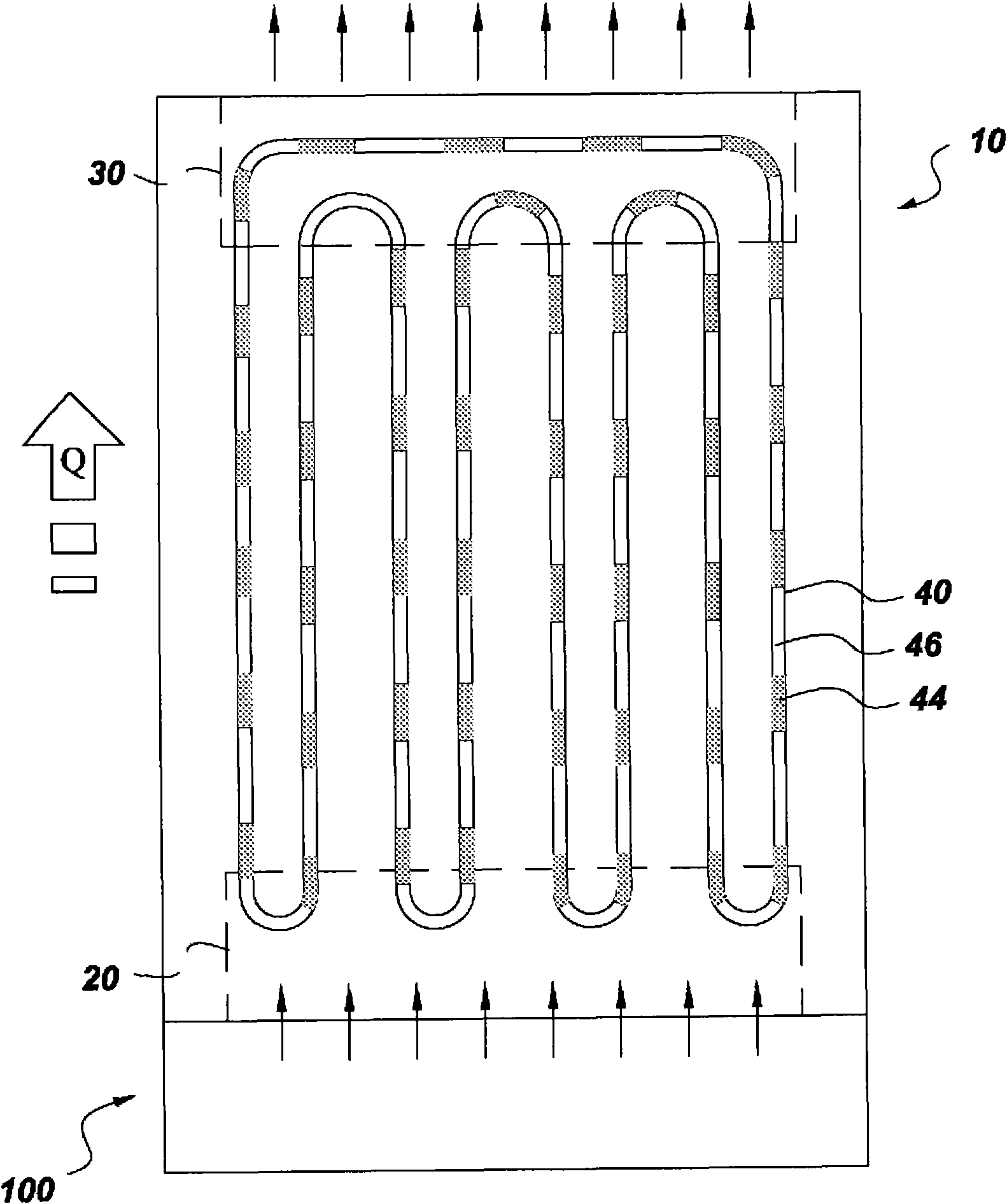
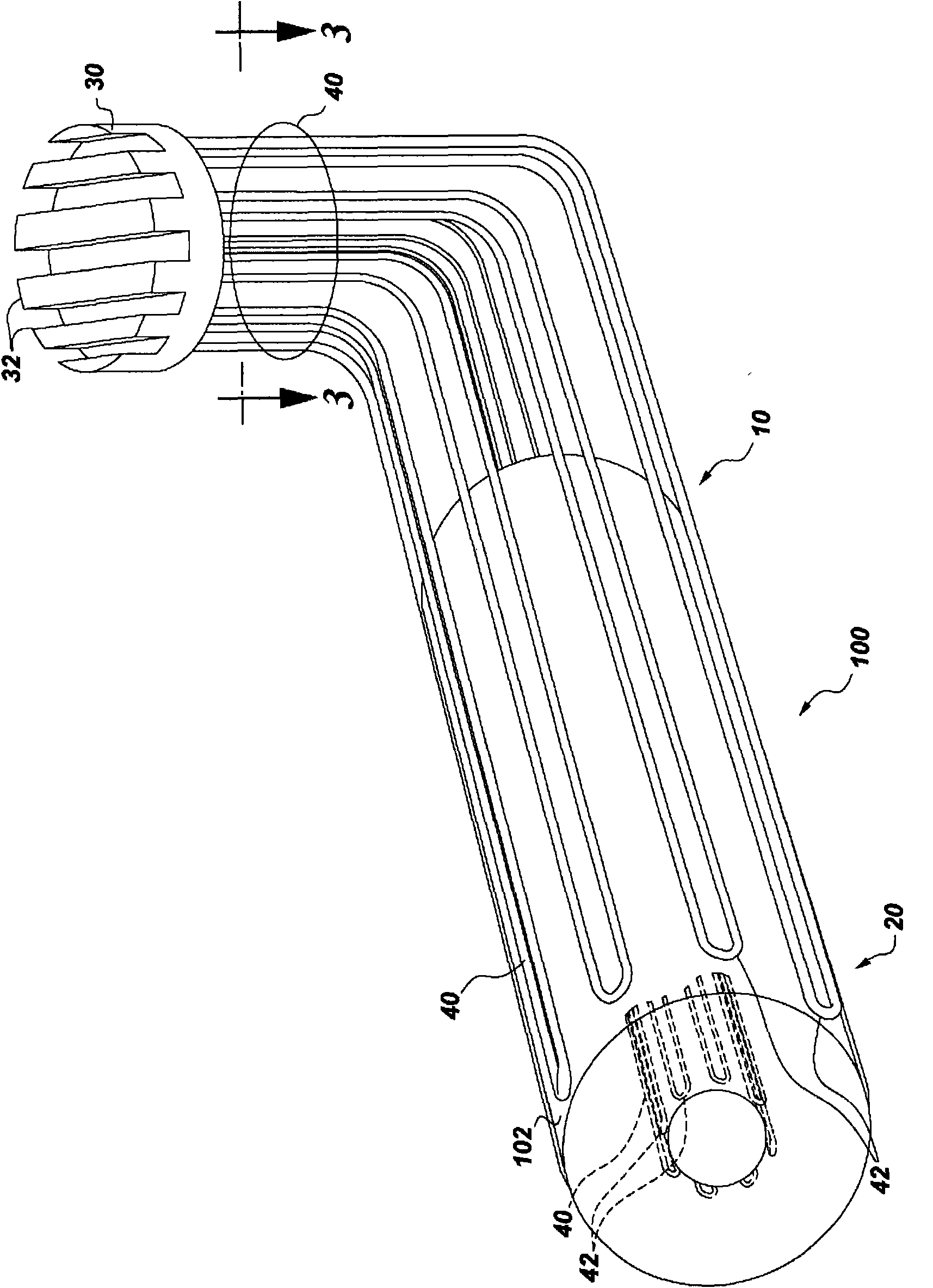
[0029] Aspects of the invention have been shown to provide advantages over previous methods of cooling superconducting magnets. The apparatus and method of the present invention require no mechanically moving parts (e.g., no pumps, no supply system for external pressure, no refrigerated "cold box" for cryogen supply, no tank supply flow for helium, etc.). The cooling method is orientation independent which benefits the design, final physical volume and footprint of the superconducting magnet assembly. Design integration of piping within existing superconducting magnet geometries is simplified. Furthermore, any hot spots that may arise are immediately corrected by the pulsating slug flow provided by the pulsating heat pipes employed in aspects of the present invention. Additional advantages provided by the design are that no expensive helium bath cooling is required and no cryogen is lost during the quench. The proposed capillary tubing can withstand high pressures of severa...


PUM


Abstract

A superconducting magnet assembly 100 and method of cooling a superconducting magnet assembly 100 includes thermally connecting a pulsating heat pipe (10) to the superconducting magnet assembly 100 and adding a liquid cryogen to the pulsating heat pipe 10. The superconducting magnet assembly 100 also includes a thermally conductive coil former 102, at least one superconducting solenoid magnet comprising at least one superconducting winding wrapped about the coil former 102 and configured to generate a magnetic field, and at least one pulsating heat pipe 10 thermally connected to the at least one superconducting solenoid magnet.

Description

[0001] Cross References to Related Applications [0002] This application relates in some respects to commonly owned serial number 226913-1, entitled "APPARATUS AND METHODFOR COOLING A SUPERCONDUCTING MAGNETIC AS SEMBLY" US Patent Application Ser. No. 12 / 415,357, which was filed concurrently with this application, and is incorporated herein by reference in its entirety. technical field [0003] The present invention relates generally to cooling of superconducting magnets, and more particularly to superconducting magnet assemblies and processes for cooling superconducting magnet assemblies. Background technique [0004] Various systems utilize superconducting magnets to generate a strong, uniform magnetic field into which an object or, in the case of an MRI system, a patient is placed. Magnetic gradient coils and radio frequency transmit and receive coils then affect the gyromagnetic material of the subject to excite signals that can be used to form useful images. Systems u...

Claims


Application Information

Patent Timeline
Patent Type & Authority Applications(China)
IPC IPC(8): H01F6/04H01F6/00
CPCG01R33/3815H01F5/02H01F6/04G01R33/3804H01F6/00F28D15/0266Y02P80/10
Inventor E·W·施陶特纳
Owner GENERAL ELECTRIC CO
Why Eureka
Try Eureka