Bridgeless power factor correcting circuit for critical continuous current mode and method thereof

A power factor correction and circuit technology, which is applied to circuits, high-efficiency power electronic conversion, output power conversion devices, etc., can solve problems such as increased conduction loss, slow decline slope of inductor current, and misoperation of MOSFETs.

Active Publication Date: 2010-10-13
DELTA ELECTRONICS INC +1
View PDF0 Cites 30 Cited by
  • Summary
  • Abstract
  • Description
  • Claims
  • Application Information

AI Technical Summary

Problems solved by technology

When the amplitude of the inductor current is small, the signal is easily interfered by noise, causing the MOSFET to conduct a false action and lose the zero-voltage conduction condition; when the input voltage is high, the slope of the inductor current is very slow, due to the detection threshold (threshold value) is very small, before the inductor current drops to zero, the MOSFET is turned on, which increases the conduction loss

Method used


Image

  • Bridgeless power factor correcting circuit for critical continuous current mode and method thereof
  • Bridgeless power factor correcting circuit for critical continuous current mode and method thereof
  • Bridgeless power factor correcting circuit for critical continuous current mode and method thereof

Examples


Embodiment Construction

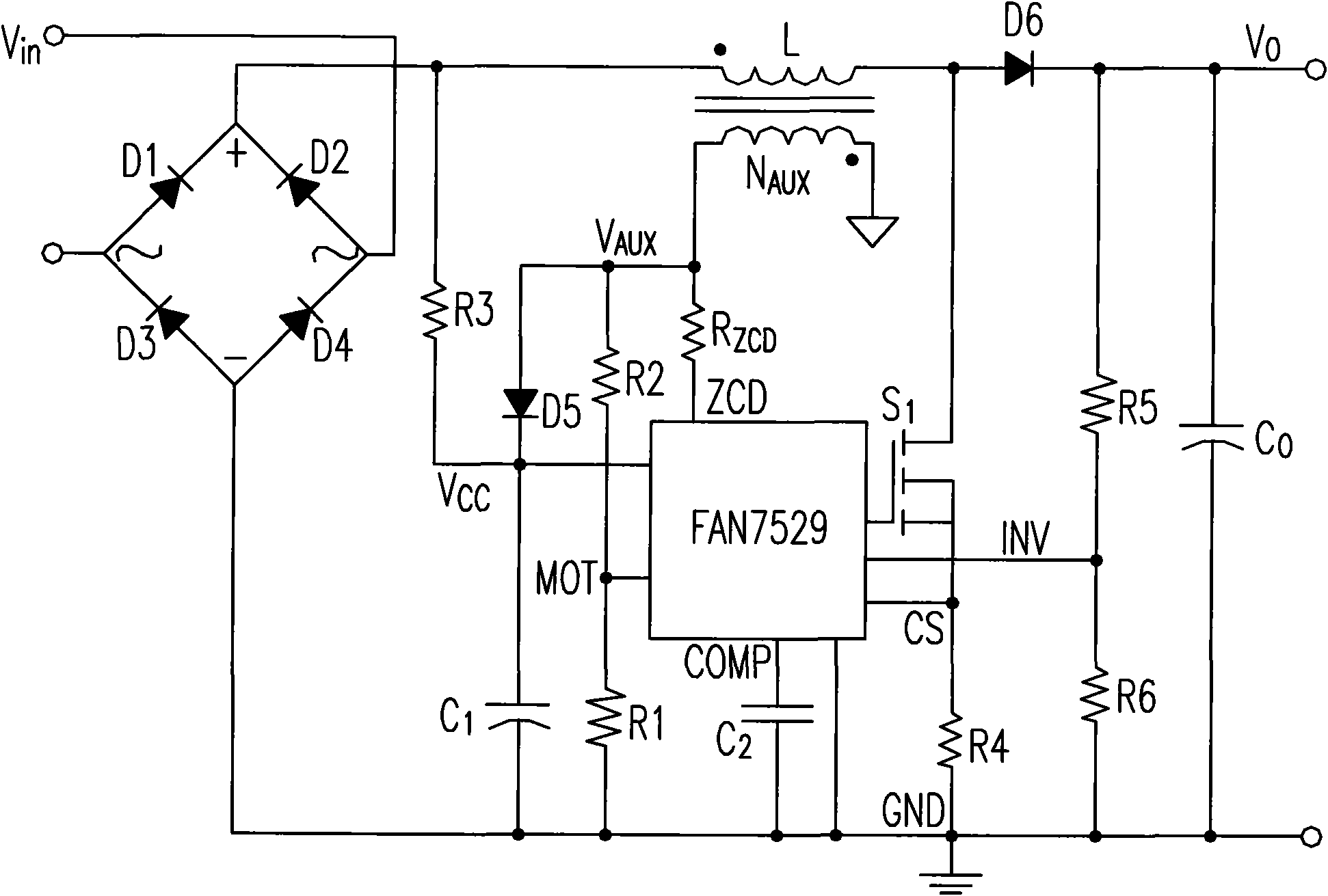
[0044] Figure 7 A H-PFC circuit utilizing an auxiliary winding for critical continuous current mode control according to a first preferred embodiment of the present invention is shown. Auxiliary winding L coupled to inductor L 1 The sensed voltage is V aux1 , since the input voltage is in the positive and negative half cycles, the voltage corresponding to the inductance L is opposite, and the auxiliary winding L 1 The induced voltage V aux1 The voltage with the inductance L is also opposite. During the positive half cycle of the input voltage, Q 3 is always on, allowing the auxiliary winding L 1 The B-terminus passes through the R 2 with Q 3 Connect to ground. During the negative half cycle of the input voltage, Q 4 is always on, allowing the auxiliary winding L 1 The A terminal passes through the R 1 with Q 4 Connect to ground. The final detection signal V ZCD Send to IC (such as L6561, FAN7528, NCP1606 and UCC38050 etc. ZCD end, Figure 7 not shown in the i...


PUM


Abstract

The invention discloses a bridgeless power factor correcting circuit and a control method thereof. The circuit comprises a switch module which allows current to flow in double directions, an inductor, and an auxiliary winding which is coupled with the inductor and generates a sense signal, wherein the sense signal is used for generating an inductive current detection signal; and when a value of the inductive current detection signal is the preset value, the switch module which allows the current to flow in the double directions is switched on.

Description

technical field [0001] The invention relates to a bridgeless power factor correction circuit (Bridgeless PFC Circuit) for a critical continuous current mode (Critical Continuous Current Mode) and a control method thereof, which can be used to solve the control problem of the critical continuous current mode of the bridgeless PFC. Background technique [0002] In the traditional boost (Boost) PFC circuit, the loss of the rectifier bridge becomes one of the main losses of the whole switching power supply. As the requirements for conversion efficiency increase, the bridgeless Boost topology derived from the traditional Boost PFC topology has gradually become a research hotspot. It omits the rectifier bridge at the front end of the traditional Boost PFC, thus reducing the on-state loss of a diode and improving efficiency. H-Power Factor Correction (H-PFC) is a bridgeless PFC topology suitable for medium and high power (see figure 1 ). exist figure 1 , the bridgeless PFC rece...

Claims


Application Information

Patent Timeline
Patent Type & Authority Applications(China)
IPC IPC(8): H02M1/42H01F38/14
CPCY02B70/126Y02B70/10
Inventor 金红元甘鸿坚
Owner DELTA ELECTRONICS INC
Why Eureka
Try Eureka