
Stem cutting device for harvesting machine

A cutting device and harvester technology, applied in the direction of harvesters, cutters, crop processors, etc., can solve the problems of unfavorable soil absorbing its nutrients, nutrients easily absorbed by soil, and stems easily rotted by soil, etc., and achieve high efficiency. , the effect of easy maintenance

Inactive Publication Date: 2010-10-20
江苏宇成动力集团有限公司
View PDF0 Cites 7 Cited by
  • Summary
  • Abstract
  • Description
  • Claims
  • Application Information

AI Technical Summary

Problems solved by technology

[0002] In the past, the harvester directly discarded the stems after the grains were harvested into the field from the cover plate on the harvester. Such a long overall stem is not conducive to the soil to absorb its nutrients. If many small pieces are thrown into the soil, the small pieces of stems are easily rotted by the soil, and the nutrients are easily absorbed by the soil, so it should be designed for the stem cutting device of the harvester.

Method used

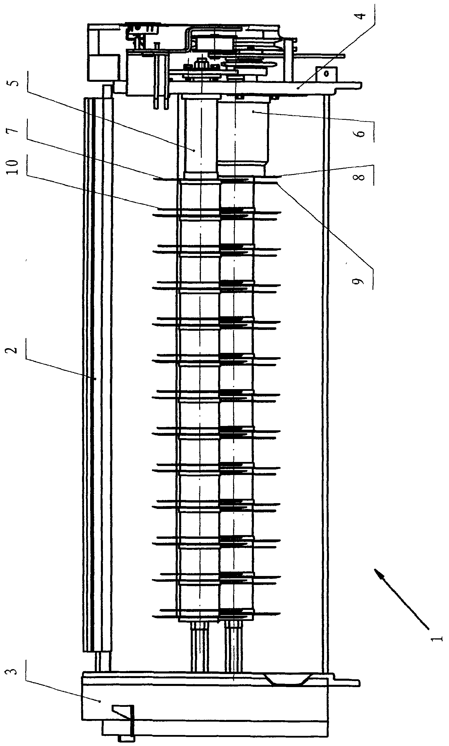
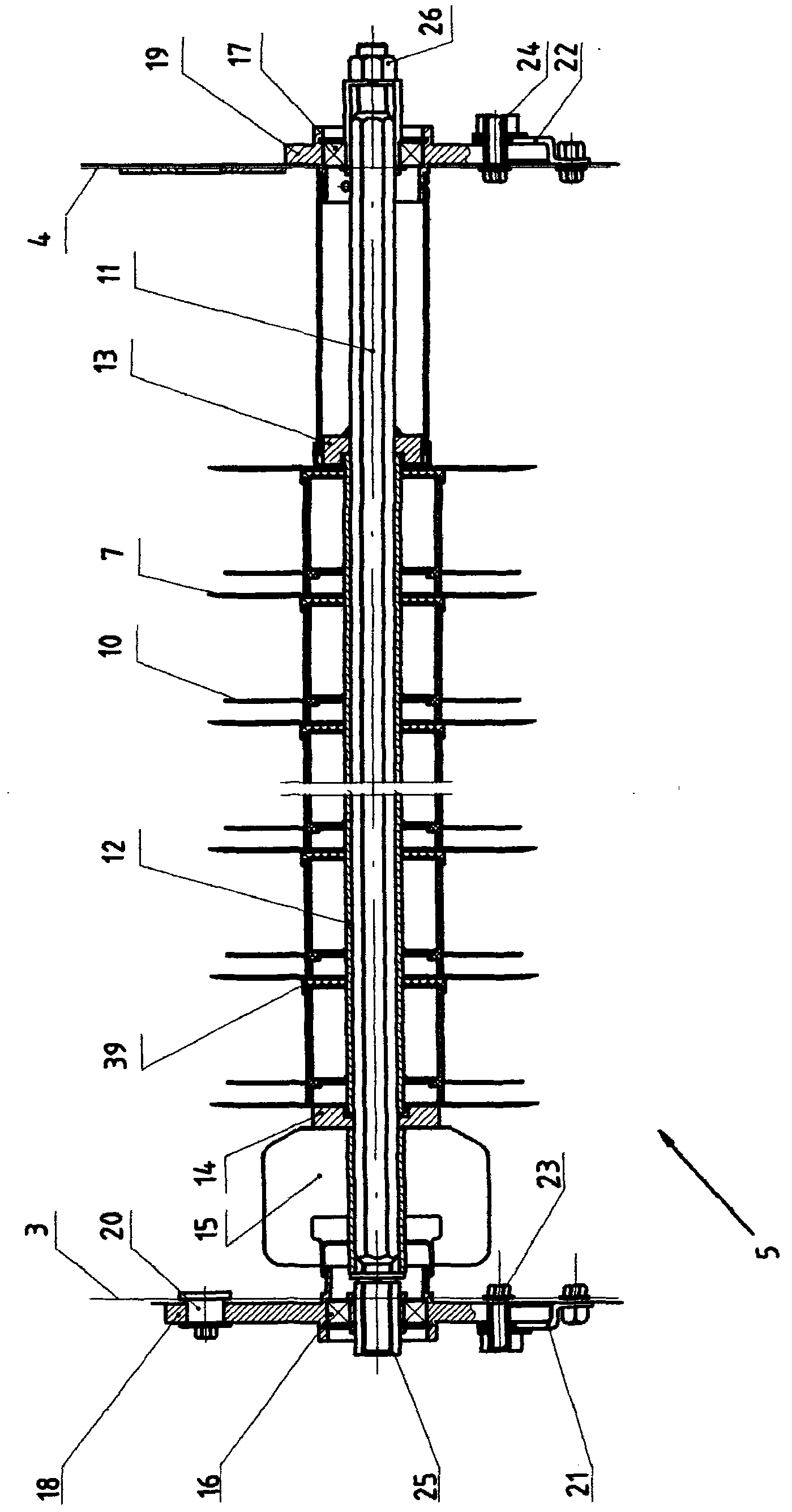
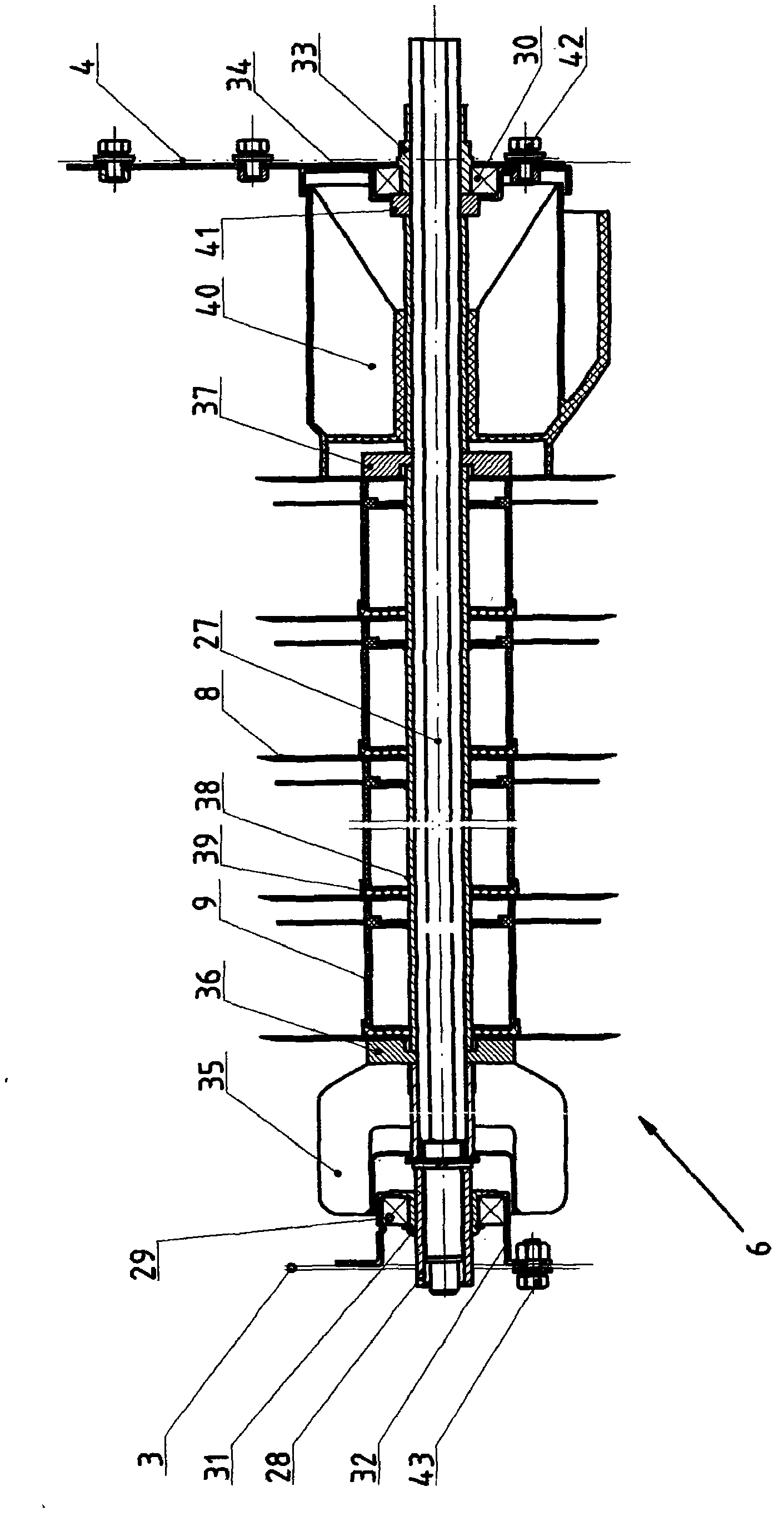

Image

  • Stem cutting device for harvesting machine
  • Stem cutting device for harvesting machine
  • Stem cutting device for harvesting machine

Examples


Embodiment Construction

[0037] see figure 1 , The stalk cutting device 1 is made up of flip cover assembly 2, left side plate welding 3, right side plate welding 4, conveying knife shaft assembly 5, and grass cutting shaft assembly 6.

[0038] see figure 2 , the left and right ends of the conveying cutter shaft 11 of the conveying cutter shaft assembly 5 are respectively installed in the left bearing 16 and the right bearing 17, and the left bearing 16 and the right bearing 17 are respectively installed in the left bearing seat 18 and the right bearing seat 19, and the left bearing seat 18 And the right bearing seat 19 is respectively installed and fixed on the left side plate welding 3 and the right side welding 4 through the left pressing plate 21 and the right pressing plate 22, and the left bearing seat bolt 20 and the left pressing plate are respectively worn on the upper and lower parts of the left bearing seat 18 Bolts 23 make the left bearing seat 18 be installed on the left side plate weld...


PUM


Abstract

The invention relates to a stem cutting device for a harvesting machine, belonging to the field for the stem cutting device. A left hook (46) and a right hook (47) which are respectively arranged on two sides of a turnover cover (45) which can be sleeved on a turnover cover rotating shaft (44) are respectively matched with a left hook mounting hole and a right hook mounting hole which are arranged on a left hook mounting plate and a right hook mounting plate; a hexagonal sleeve pipe (12) for a delivering tool axis (11), which is sleeved on the delivering tool axis (11), is provided with a blade (7) for the delivering tool axis (11), a grass scraping assembly (10) for the delivering tool axis (11), a cover (39), a positioning block (13) on the right end of the blade (7) for the delivering tool axis, a positioning block (14) on the left end of the blade (7) for the delivering tool axis and a stem triggering-in wheel (15); a hexagonal sleeve pipe (38) for a cutting tool axis is provided with a blade (8) for the cutting tool axis, a grass scraping assembly (9) for the cutting tool axis, the cover (39), a positioning block (36) on the left side of the blade (8) for the cutting tool axis, a positioning block (37) on the right side of the blade (8) for the cutting tool axis, a left grass discharging rolling wheel and a right grass discharging rolling wheel, wherein the left grass discharging rolling wheel and the right grass discharging rolling wheel are welded together; and a left plate welding assembly (3) and a right plate welding assembly (3) are respectively arranged on the left side and the right side. The stem cutting device for the harvesting machine has high efficiency and is convenient for maintenance and installation.

Description

Technical field: [0001] The invention discloses a harvester stalk cutting device, which relates to the field of cutting devices for cutting the stalk after the harvester finishes beating grains. Background technique: [0002] In the past, the harvester directly discarded the stems after the grains were harvested into the field from the cover plate on the harvester. Such a long overall stem is not conducive to the soil to absorb its nutrients. Many small sections are thrown into the soil again, then the small section stems are easily rotted by the soil, and its nutrients are easily absorbed by the soil, so the stem cutting device should be designed for harvesters. Invention content: [0003] The purpose of the present invention is to provide a harvester stalk cutting device, which cuts the stalk into several small sections by the blades on the conveying knife shaft assembly and the grass cutting knife shaft assembly, and throws them into the soil to reach the stalk The rod...

Claims


Application Information

Patent Timeline
IPC IPC(8): A01D43/08A01D82/00
Inventor 蒯杰朱梅生
Owner 江苏宇成动力集团有限公司
Learn More