

Mechanism for mounting and adjusting spray heads of inkjet printer
An inkjet printer, installation and adjustment technology, applied in printing, transfer materials, power transmission devices, etc., can solve problems such as difficult to meet the adjustment accuracy requirements, troublesome adjustment, mechanism deviation, etc., and achieve simplification and saving of maintenance work The effect of adjusting time and ensuring accuracy
- Summary
- Abstract
- Description
- Claims
- Application Information
AI Technical Summary
Problems solved by technology
Method used
Image

Examples
Embodiment Construction
[0039] A specific embodiment of the present invention will be described in detail below in conjunction with the accompanying drawings.
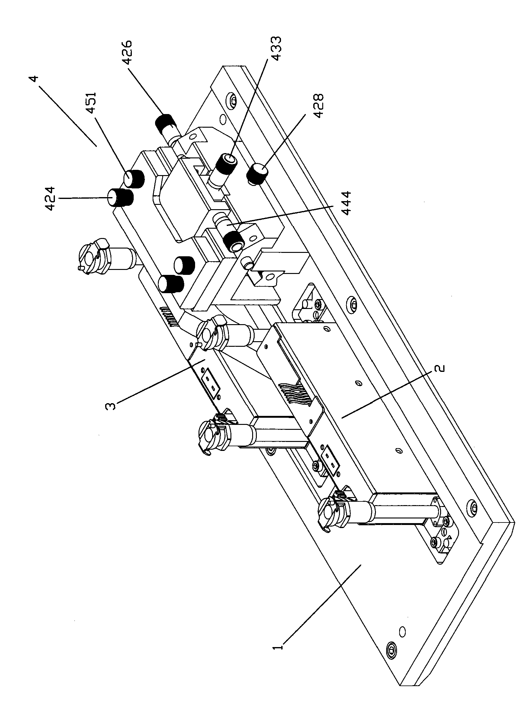
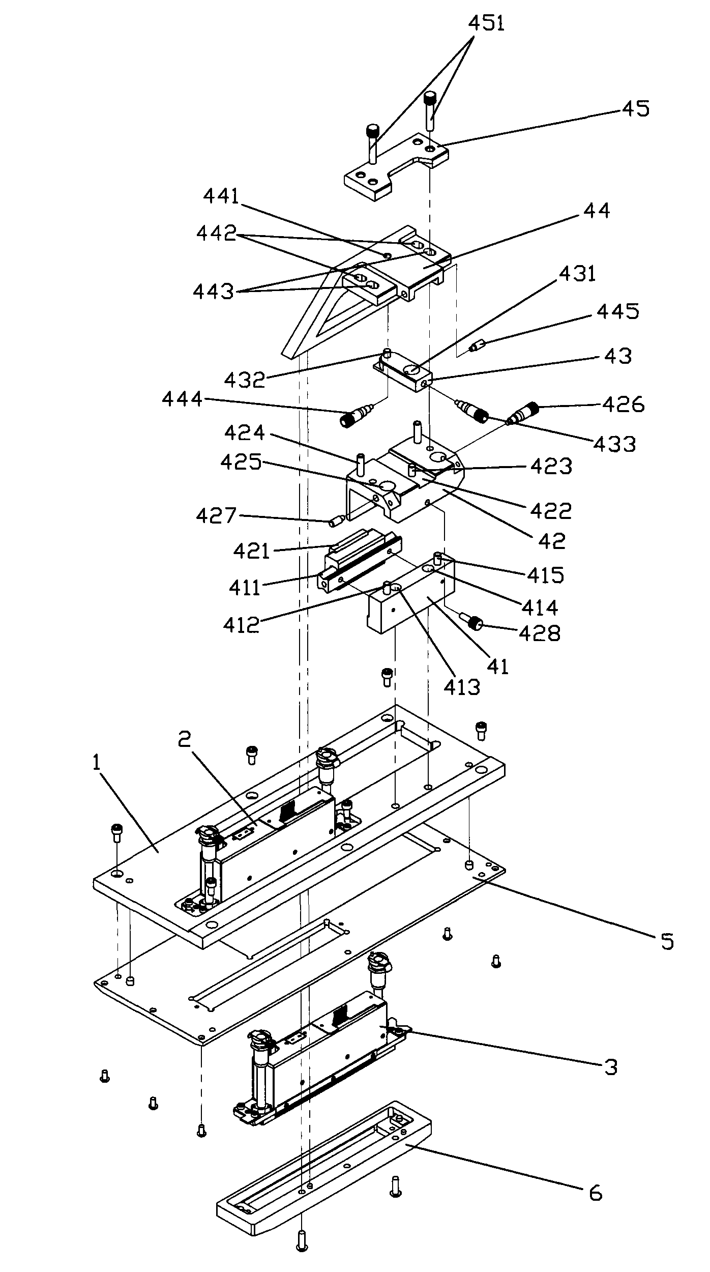
[0040] Such as Figure 2-5As shown, the nozzle installation and adjustment mechanism of the inkjet printer of the present invention includes a base plate 1 and an adjustment mechanism 4, the base plate 1 is provided with nozzle installation holes 11, 12, and the two ends of the nozzle installation hole 11 in the length direction are respectively provided with a positioning cylindrical pin 111, 112. One end of the nozzles 2 and 3 is provided with a V-shaped positioning gap, and the other end is provided with an L-shaped positioning gap. The V-shaped and L-shaped gaps of the nozzle 2 are respectively matched with the positioning cylindrical pins 111 and 112 provided on the bottom plate 1 to align the nozzles. 2. Fixedly installed at the installation hole 11 of the nozzle; the nozzle 3 is installed at the through hole 61 of the installation plat...
PUM
 Abstract
Description
Claims
Application Information