

Method for separating and picking up flat lenses and device thereof
A pick-up device and lens technology, which is applied in the directions of pile separation, object separation, transportation and packaging, etc., to achieve the effect of improving operating efficiency and reducing production costs
- Summary
- Abstract
- Description
- Claims
- Application Information
AI Technical Summary
Problems solved by technology
Method used
Image

Examples
Embodiment 1
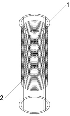
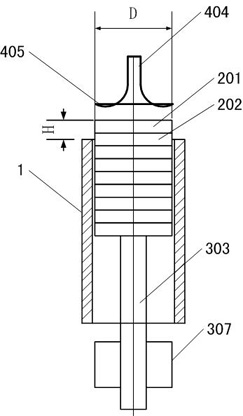
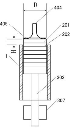
[0020] Embodiment 1: This embodiment provides a method for separating and picking up flat lenses, as attached figure 2 , attached image 3 , attached Figure 4 , attached Figure 5 As shown, a method for separating and picking up flat lenses provided in this embodiment includes: placing the flat lenses 2 that are in a state of being adhered to each other in a vertically erected lens barrel 1, and stacking the entire vertically erected lens barrel 1 in a form The plate lens 2 in the adhesion state rises to the position where the uppermost plate lens 201 exceeds the exit plane of the upper end of the lens barrel 1, and the distance H is greater than the thickness of one plate lens 2 and less than the thickness of two plate lenses 2; a vacuum suction is provided for suction The rod 404 makes its suction head 405 pick up and hold the uppermost flat lens 201, and then makes the suction rod 404 move horizontally with the flat lens 201 picked up and held by its suction head 405, a...
Embodiment 2
[0023] Embodiment 2: Based on the method provided in Embodiment 1, the inventors of the present invention propose a device for separating and picking up flat lenses in this embodiment. Such as figure 2 , image 3 , Figure 4 , Figure 5 , Image 6 , Figure 7 , Figure 8 As shown, a device for separating and picking up a flat lens in this embodiment includes a lens pushing device, a lens picking device and a lens horizontal moving device.
[0024] The function of the lens pushing device is to make the uppermost flat lens 201 of the flat lens 2 stacked in the vertical standing lens barrel 1 and in the adhered state reach a predetermined position, that is, the uppermost flat lens 201 reaches the exit of the upper end of the lens barrel 1 The position of the plane is greater than the thickness of one flat lens 2 and less than the thickness of two flat lenses 2 . The lens pushing device includes a lens barrel seat member 301 , a tappet 304 , a tappet guide member 307 and a...
Embodiment 3
[0033] Embodiment 3: Based on the method provided in Embodiment 1, the inventors of the present invention proposed a device for separating and picking up flat lenses in this embodiment on the basis of Embodiment 2. In this implementation, the lens picking device also includes a mechanical arm, a vacuum generating device 408, a valve 406, a suction rod 404 and a suction head 405. The difference from the second embodiment is that the mechanical arm includes a central base The base 401 and the four poles 402 fixedly connected with the central base 401, the four suction poles 404 are respectively vertically fixed on the four poles 402, and the bottom end of each suction pole 404 is equipped with a suction lens respectively. The suction head 405 and the other end of the suction rod 404 are respectively connected to a vacuum generating device 408 through a hose 407 and a valve 406 . Of course, there may be several support rods 402 fixedly connected with the central base 401, and the...
PUM
 Abstract
Description
Claims
Application Information