
Method and electric switch for testing an energy generator or energy consumer which can be attached to an electrical energy supply network

An energy generating device and energy consumption technology, applied in the direction of measuring devices, measuring electrical variables, measuring electricity, etc., to improve the effect of testing

Active Publication Date: 2010-10-27
科孚德有限公司
View PDF5 Cites 7 Cited by
  • Summary
  • Abstract
  • Description
  • Claims
  • Application Information

AI Technical Summary

Problems solved by technology

However, the voltage drop is only possible at fixed predetermined levels and at a fixed frequency

Method used


Image

  • Method and electric switch for testing an energy generator or energy consumer which can be attached to an electrical energy supply network
  • Method and electric switch for testing an energy generator or energy consumer which can be attached to an electrical energy supply network
  • Method and electric switch for testing an energy generator or energy consumer which can be attached to an electrical energy supply network

Examples


Embodiment Construction

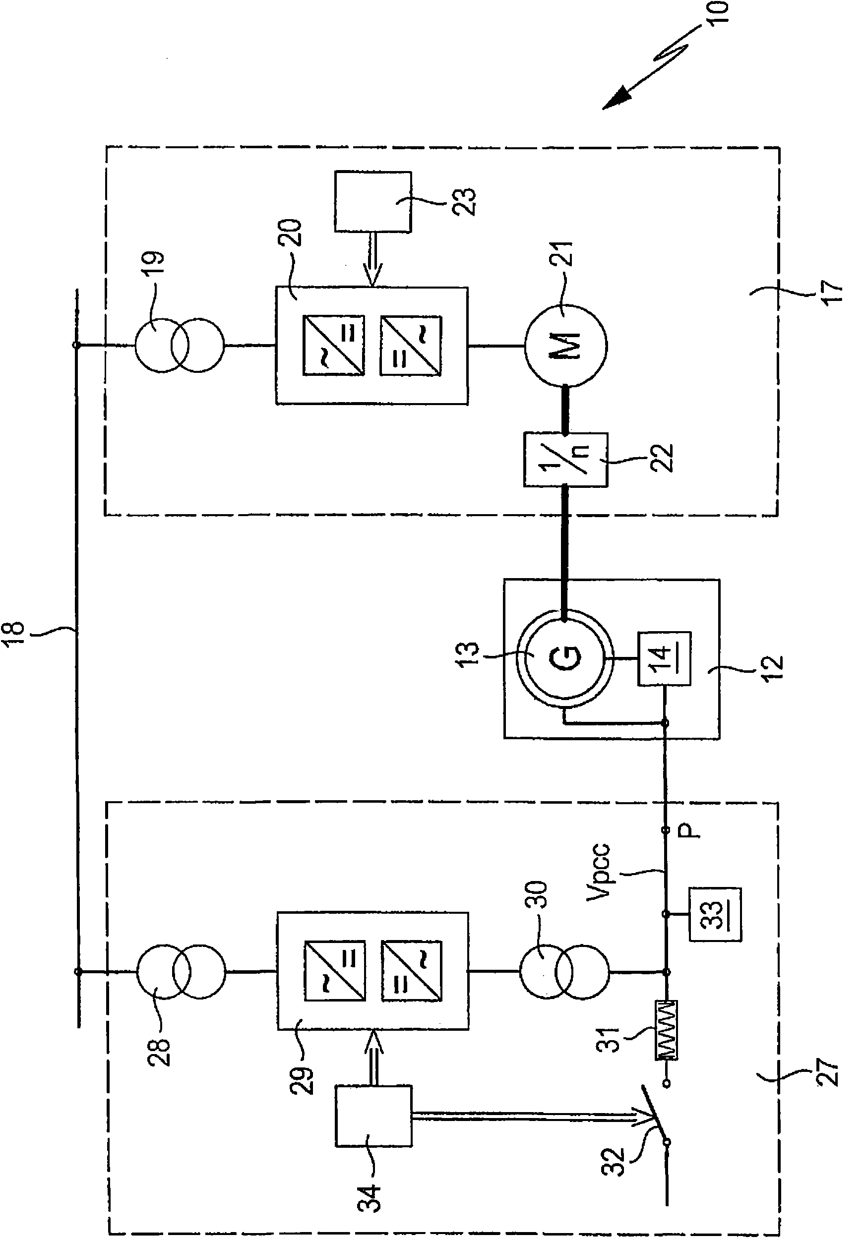
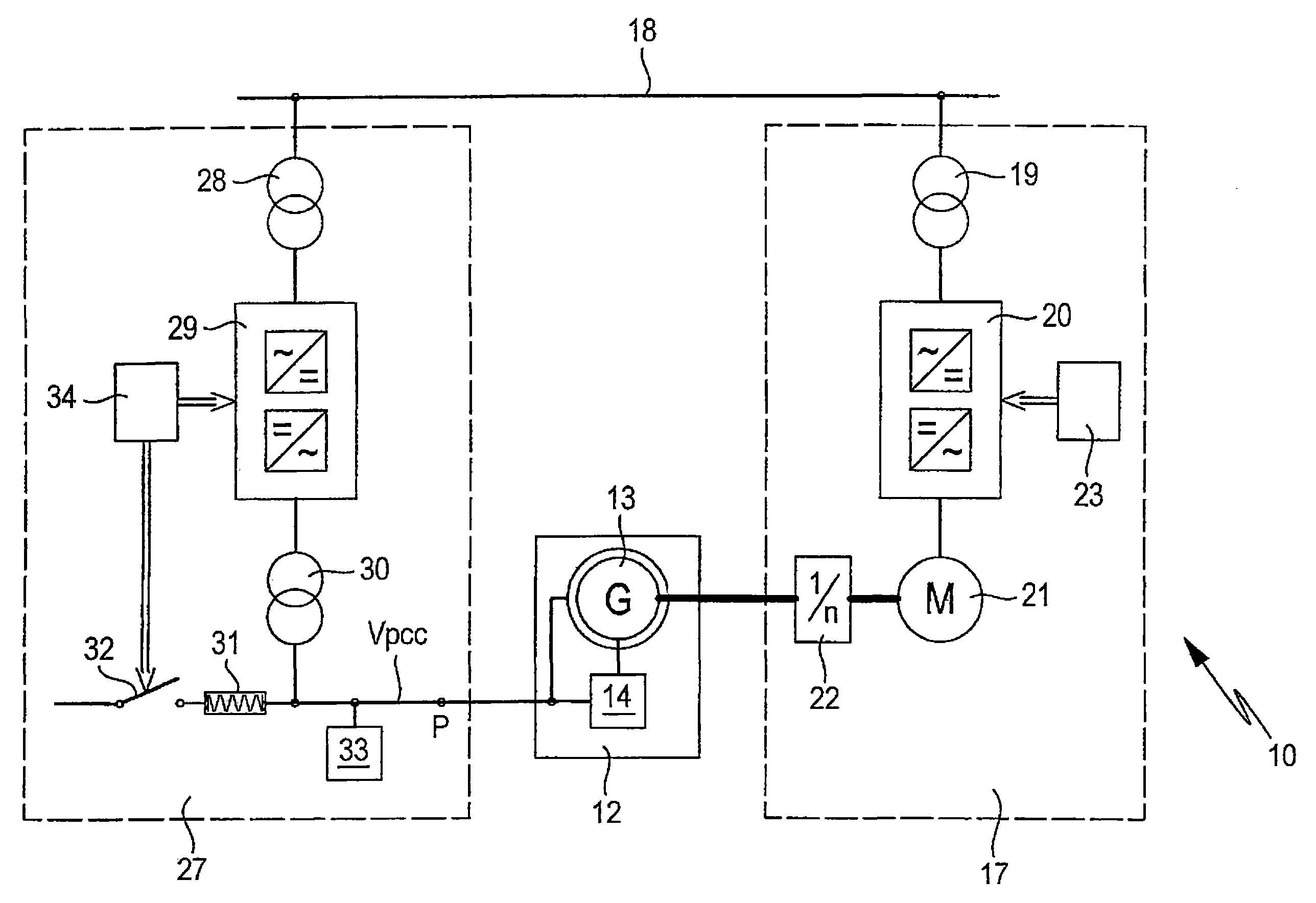
[0018] exist figure 1 A circuit 10 is shown in , which in the present embodiment is used in conjunction with a wind power plant. It should be understood that the circuit 10 can also be applied to a hydroelectric power station or a gas-fired power station or the like. Furthermore, the circuit 10 is provided in the present embodiment for testing a generator. It is understood that other energy generating or energy consuming devices can also be tested by means of the circuit 10 , for example also electric motors or fuel cells or solar inverters or so-called power conditioning systems etc. can be tested.

[0019] For simplicity, in figure 1 The circuit 10 is shown substantially only in one phase. It should be understood that the circuit 10 can also be constructed in two-phase and multi-phase configurations.

[0020] The circuit 10 has a generator circuit 12 which is to be tested. The generator circuit 12 refers to those components of the wind power plant for generating electri...


PUM


Abstract

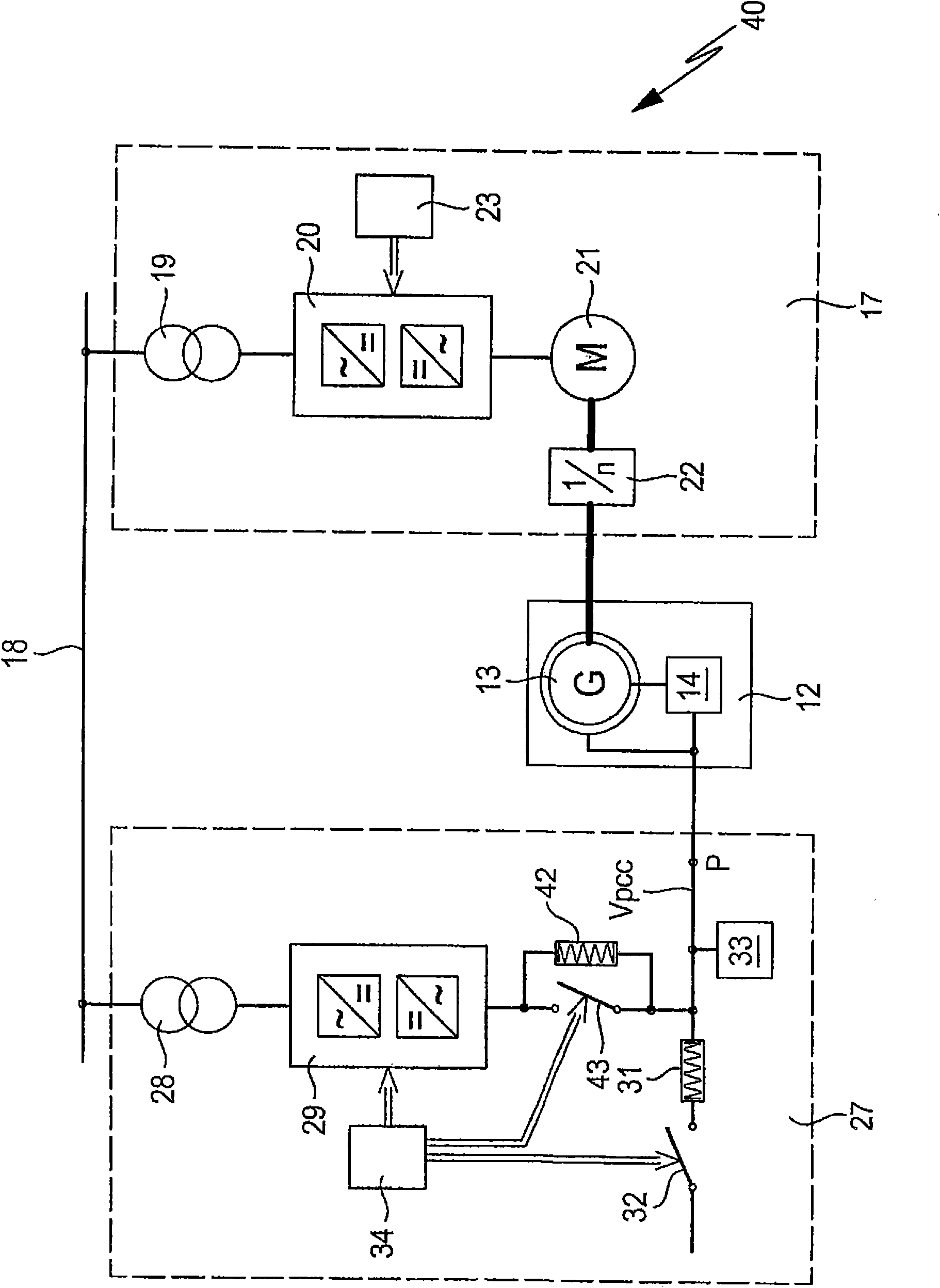
The method involves influencing voltage (Vpcc) using a converter circuit (29), where the voltage like at a connection point (P) to which an energy generator or an energy consumer is attached. A series connection is designed from an induction coil (31) and a switch (32). The series connection is coupled with the connection point. The converter circuit is influenced such that the voltage is transferred to the connection point in a desired value and the switch is closed. A parallel circuit is designed from an induction coil and another switch.

Description

technical field [0001] The present invention generally relates to methods and circuits for testing grid-connectable energy generating devices or energy consuming devices. Energy generators and energy consumers can be generators, electric motors, fuel cells, solar inverters, so-called power conditioning systems or other electrical components that can be connected to the grid. [0002] In particular, the invention relates to a method and a circuit for testing a generator of a wind power plant. It should be understood that the invention may also be used in hydroelectric or gas-fired power stations or the like. Background technique [0003] In order to generate electrical energy, wind power plants are known in which a generator is driven by means of a windmill subjected to the wind. The generated electrical energy is then fed into the grid. [0004] The operator of the grid already specifies conditions that the wind power plant must meet in order to be able to connect it to t...

Claims


Application Information

Patent Timeline
Patent Type & Authority Applications(China)
IPC IPC(8): G01R31/34
CPCH02P2009/004H01H83/04F03D7/0284Y02E10/725Y02E10/722F05B2270/10711G01R31/343G01R31/34F03D9/003F03D11/0091H02P9/102F03D9/255F03D17/00H02P2101/15Y02E10/72
Inventor C·萨尼特尔J·杨宁
Owner 科孚德有限公司
Learn More