Method and device for computing service transmission path in optical transport network

A technology of business transmission and calculation method, which is applied in the field of communication, can solve problems such as rising business blocking rate, network resource bottleneck, and reducing network resource utilization, so as to achieve the effect of reducing blocking rate and improving utilization rate

Inactive Publication Date: 2010-10-27
HUAWEI TECH CO LTD +1
View PDF0 Cites 20 Cited by
  • Summary
  • Abstract
  • Description
  • Claims
  • Application Information

AI Technical Summary

Problems solved by technology

[0007] First, the calculation method based on the transmission path of the static business in the prior art, when selecting the transmission path for the batch dynamic business, the auxiliary graph used is established based on the current batch of business, the next batch of business and the current batch of business When the source node / sink node and the traffic volume change greatly, it may cause unreasonable route selection for the next batch of services, so that the services are forced to use multi-hop optical paths based on the current virtual topology, which reduces the utilization of network resources and makes The blocking rate of the business becomes larger
[0008] Second, the calculation method based on the transmission path of a single dynamic service in the prior art is to design the calculation method of the service transmission path in the optical transport network at one time for the dynamic arrival of a single service, without considering the dynamic arrival of batch services In addition, unreasonable paths are not optimized. Corresponding to dynamically arriving batch services, differences in business models of different batches will cause differences in virtual topology, which will affect the configuration of subsequent batch services.
For uniform services, this design method has little impact on network performance; but for non-uniform services, this method is likely to cause a "bottleneck" phenomenon of network resources, resulting in an increase in the service blocking rate

Method used


Image

  • Method and device for computing service transmission path in optical transport network
  • Method and device for computing service transmission path in optical transport network
  • Method and device for computing service transmission path in optical transport network

Examples


Embodiment 1

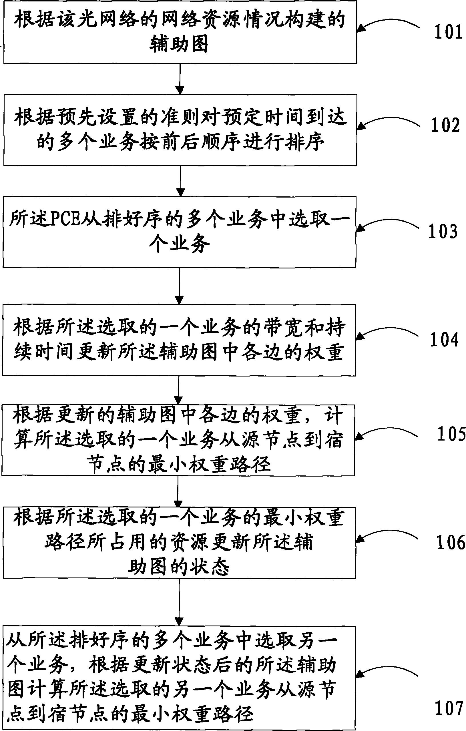
[0033] An embodiment of the present invention provides a method for calculating a service transmission path in an optical transport network, such as figure 1 As shown, the method includes:

[0034] 101. In the optical transport network, the optical network corresponds to an auxiliary graph constructed according to the network resources of the optical network, wherein the auxiliary graph is an optical transceiver in the node device in the optical network, and upper-layer traffic Network equipment constraints such as grooming capability, wavelength conversion capability, and link wavelength are transformed into edges (Edges) in the graph, which are integrated into a unique graph in the entire network; each edge in the auxiliary graph corresponds to a corresponding weight, indicating that the service passes The route selection and resource allocation of the upper-layer business at the cost of this edge are calculated once on the auxiliary graph.

[0035] 102. PCE (Path Computati...

Embodiment 2

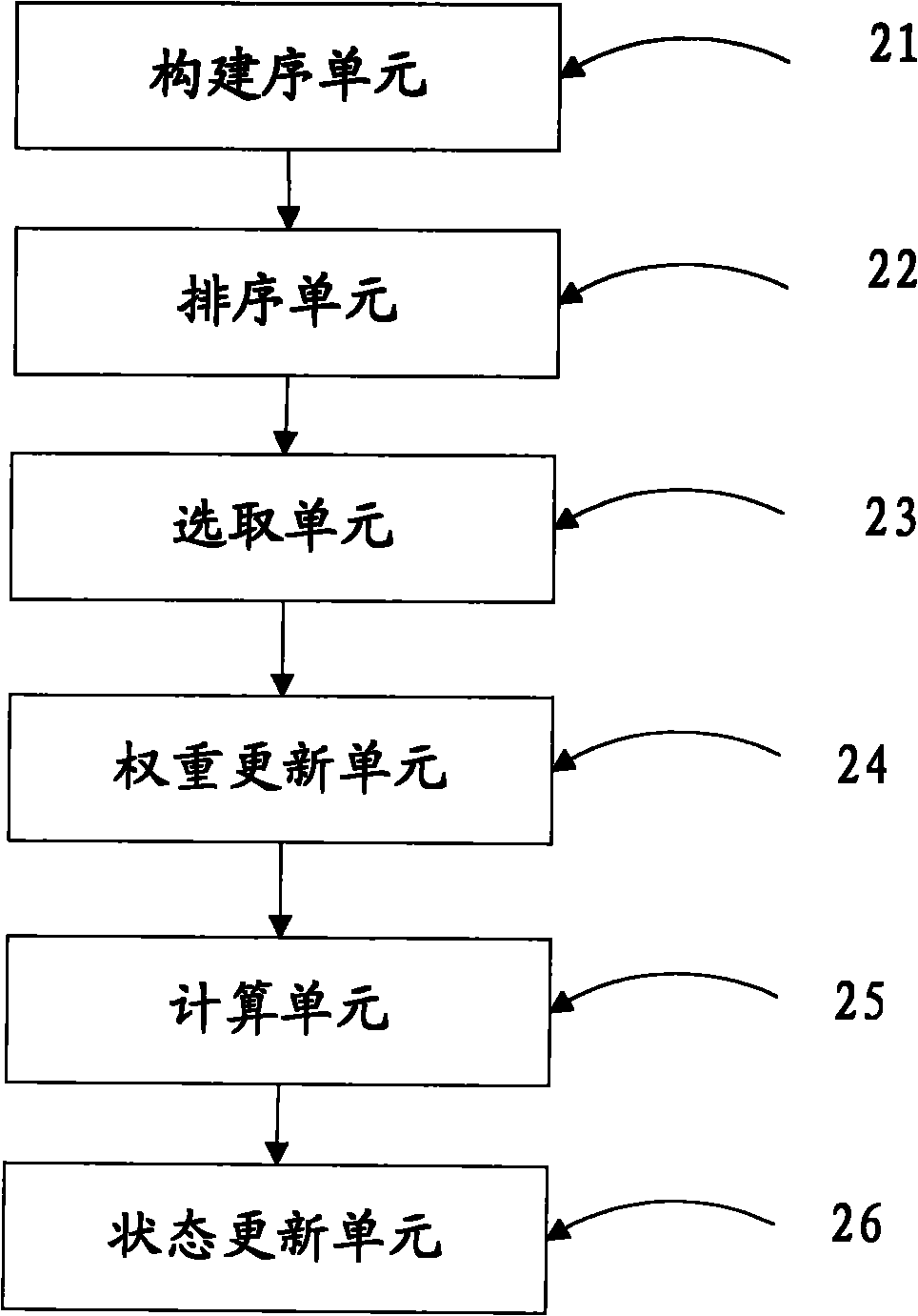
[0053] An embodiment of the present invention provides a device for calculating a service transmission path in an optical transport network. The device is specifically a PCE (Path Computation Element, Path Computation Element), such as figure 2 As shown, the device includes: a construction unit 21 , a sorting unit 22 , a selection unit 23 , a weight update unit 24 , a calculation unit 25 and a state update unit 26 .

[0054] When calculating the service transmission path in the optical transport network, the PCE first constructs an auxiliary graph according to the network resource conditions of the optical network through the construction unit 21, wherein the auxiliary graph is a node device in the optical network Network equipment constraints such as optical transceivers, upper-layer traffic grooming capabilities, wavelength conversion capabilities, and link wavelengths are transformed into edges (Edges) in the graph, and integrated into a unique graph of the entire network; ...

Embodiment 3

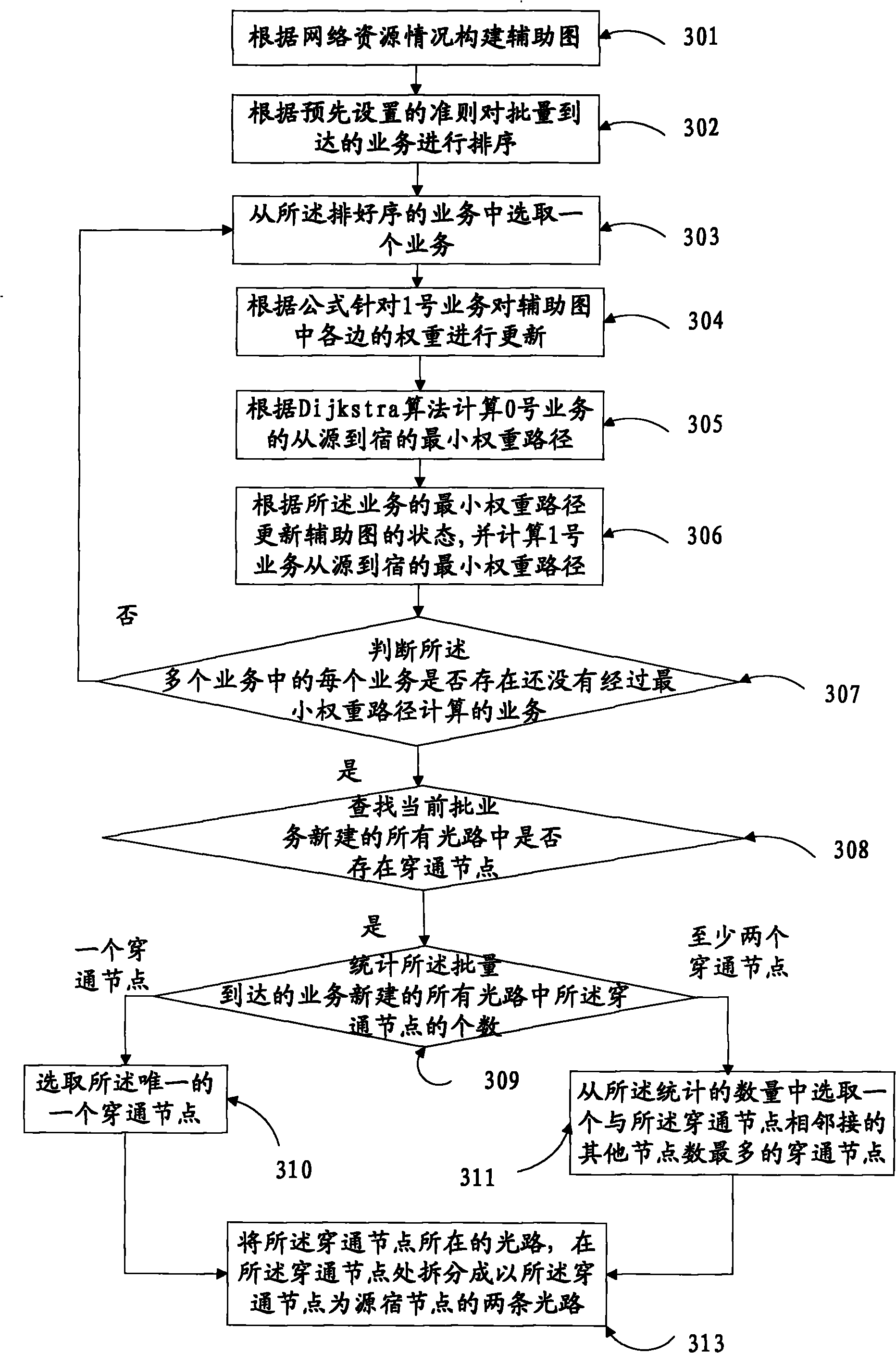
[0068] An embodiment of the present invention provides a method for calculating a service transmission path in an optical transport network, such as image 3 As shown, the method includes:

[0069] 301. An auxiliary graph constructed according to the network resource situation of the optical network, each edge in the auxiliary graph corresponds to a corresponding weight, indicating the cost when the service passes through the edge; the network resource situation refers to the number of wavelengths in the optical fiber and the upper-layer business grooming capabilities of each node in the network.

[0070] The embodiment of the present invention takes six nodes in the network and the number of optical fiber wavelengths as W as an example to construct an auxiliary graph. For the convenience of service route selection, the auxiliary graph is abstracted into a virtual topology graph, as shown in Figure 4 As shown in , there is only one wavelength on each side of the virtual topo...


PUM


Abstract

The embodiment of the invention discloses a method and a device for computing a service transmission path in an optical transport network. The invention solves the problem of low utilization ratio of network resources due to high blocking rate of service transmission in the network. The method comprises the following steps of: sequencing a plurality of services which arrive according to the preset standard scheduled time in time sequence; selecting one service from the sequenced services in time sequence at a time; and updating the weight of each edge in the auxiliary chart according to the bandwidth and duration time of the selected service, computing the minimum weight path of the selected service from the source node to the destination node according to the weight of each edge in the updated auxiliary chart, and updating the state of the auxiliary chart according to the resources occupied by the minimum weight path of the selected service. The embodiment of the invention is mainly used in the field of communication, and especially in the computation process of the service transmission path in the optical transport network.

Description

technical field [0001] The invention relates to the communication field, in particular to a calculation method and device for a service transmission path in an optical transport network. Background technique [0002] WDM (Wavelength Division Multiplexing, wavelength division multiplexing) technology has been widely used in optical networks, especially in optical transport networks. At present, the bandwidth of a single wavelength can reach the Gbit level, such as 0C-48, 0C-192 and 0C-768 (the corresponding bandwidths are 2.5Gbps, 10Gbps and 40Gbps respectively); however, the bandwidth requests of upper-layer services in the actual operating network are often less than one The bandwidth provided by the wavelength, such as 0C-1, 0C-3, and 0C-12 (the corresponding bandwidths are 51.84Mbps, 155.52Mbps, and 622.08Mbps respectively). Comparing the two, it can be found that there is an obvious bandwidth difference between the bandwidth of the wavelength in the WDM network and the ...

Claims


Application Information

Patent Timeline
Patent Type & Authority Applications(China)
IPC IPC(8): H04L12/56H04Q11/00H04J14/02H04L12/721
Inventor 章小宁吴健廖丹孙俊
Owner HUAWEI TECH CO LTD
Why Eureka
Try Eureka