QoS (Quality of Service) route distributing method for realizing load balance in overlay network

A load balancing and overlay network technology, applied in the field of network communication, can solve problems such as congestion, network paralysis, single-ended links or high resource consumption rate of nodes

Inactive Publication Date: 2011-05-11
WUHAN UNIV
View PDF3 Cites 20 Cited by
  • Summary
  • Abstract
  • Description
  • Claims
  • Application Information

AI Technical Summary

Problems solved by technology

However, such methods still have some unfairness, mainly because they do not consider resource bottlenecks of links and nodes with local heavy loads.
The overlay network service path is composed of multiple overlay links and overlay nodes. However, the capabilities of these links and nodes are also unbalanced. Although the overall consumption cost of o

Method used


Image

  • QoS (Quality of Service) route distributing method for realizing load balance in overlay network
  • QoS (Quality of Service) route distributing method for realizing load balance in overlay network
  • QoS (Quality of Service) route distributing method for realizing load balance in overlay network

Examples


Embodiment

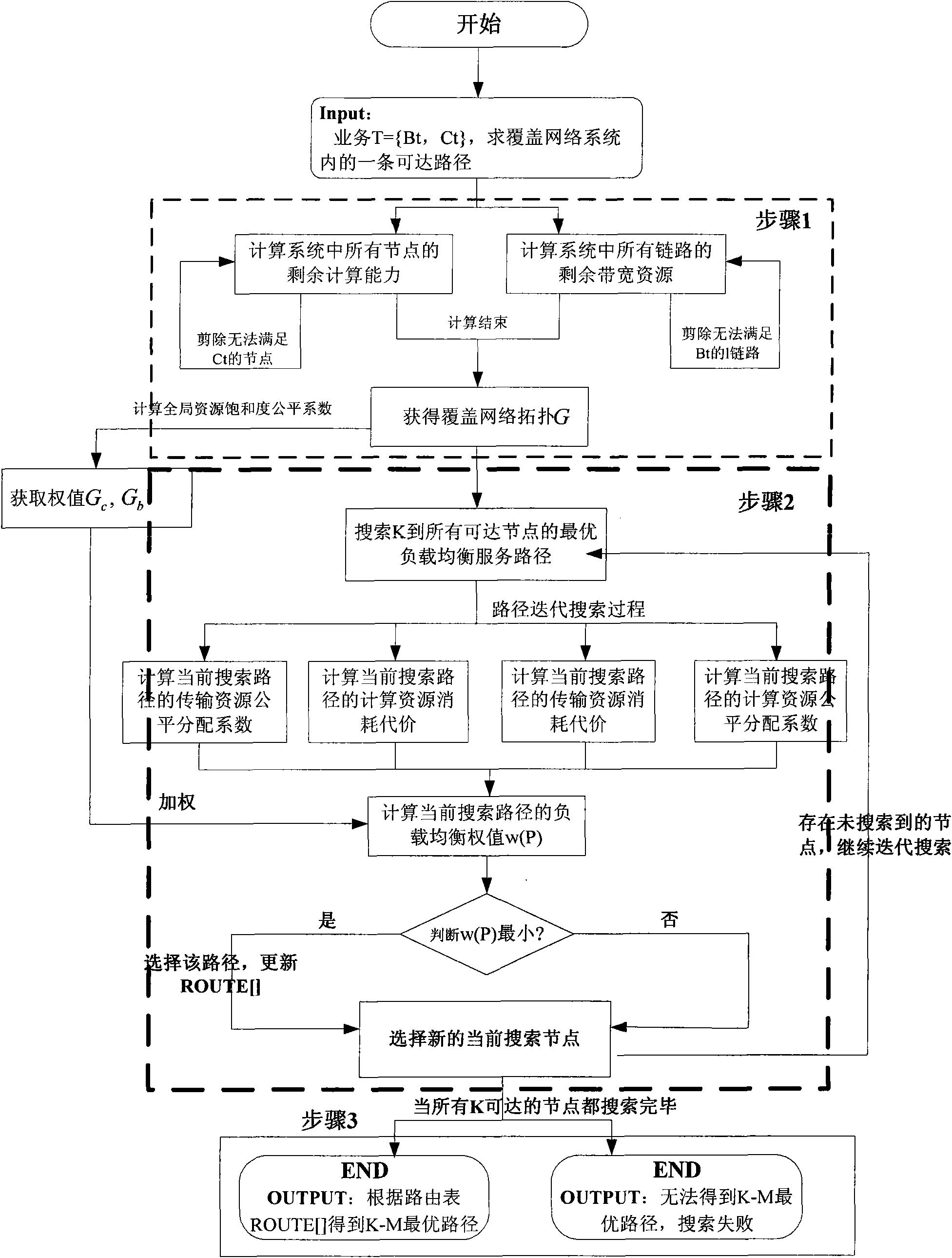
[0076] Embodiment Comprehensive formula (1) (2) (3) (4) obtains the load balancing weight w (P) of the searched service path P according to formula (7) (8) calculation result,

[0077] w ( P ) = G c G c + G b × ΔB ( P ) f B ( P ) + G b G c + G b × ΔC ( P ) f ...


PUM


Abstract

The invention relates to the technical field of network communication, in particular to a QoS (Quality of Service) route distributing method for realizing load balance in an overlay network. The method comprises the steps of: introducing resource fair index representing path bottleneck degree, establishing a new load balance utility function, correcting a QoS bound term weight by adopting an adaptive system load state weighting method, and searching an optimal load balance service path. Compared with the traditional route method for load balance in the overlay network, the invention has the advantages of lowering the fluctuation degree RLCD (Residual Link Capacity Deviation) and RNCD (Residual Node Capacity Deviation) of the network load distribution, and being capable of improving the QoS service success rate (QSSR).

Description

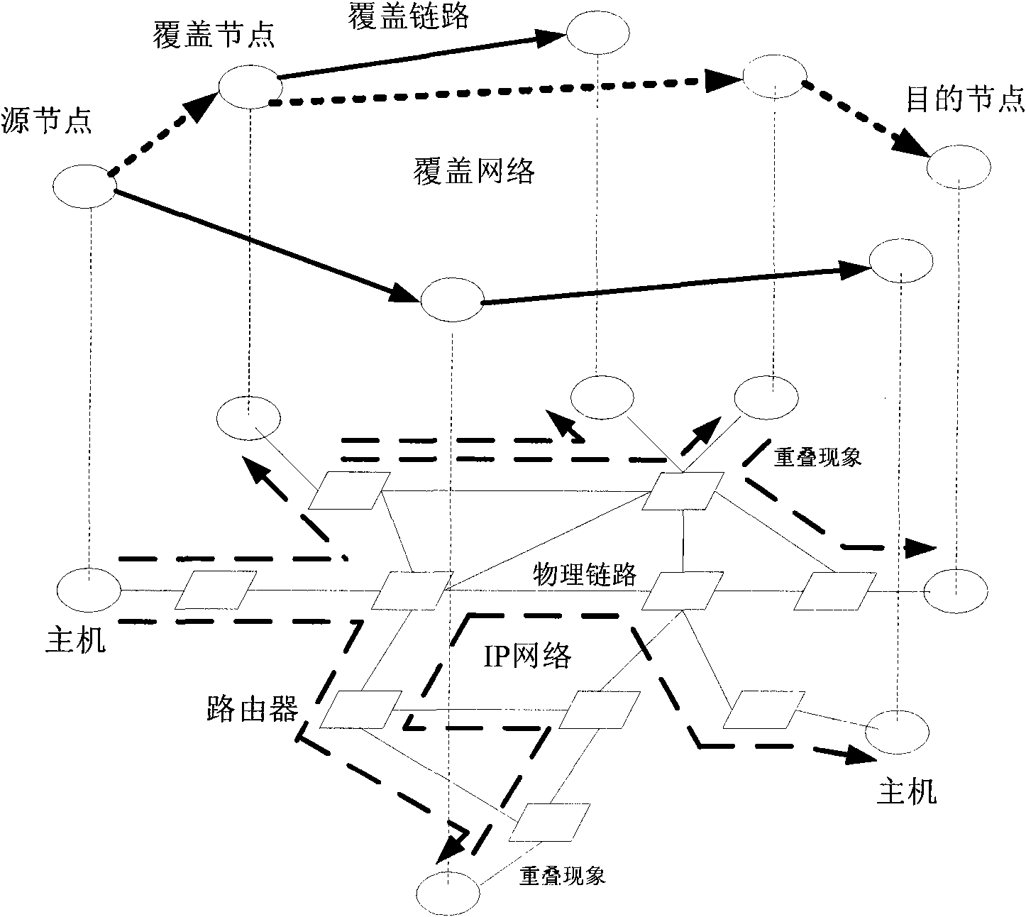
technical field [0001] The invention relates to the technical field of network communication, in particular to a QoS routing distribution method for realizing load balancing in an overlay network. Background technique [0002] Overlay network technology refers to a virtual application layer network formed by setting up intelligent nodes at key positions of the basic network and connecting them in a unicast routing manner. This network is located between the user terminal and the physical network and can be used to implement specific application. Compared with the underlying basic network, the overlay network layer can monitor status information such as routing direction, transmission delay, traffic distribution, congestion, abnormal faults, and virus infection on the underlying network. On the one hand, the overlay network layer relies on overlay nodes to exchange these information with each other, and on the other hand, it implements intelligent control and management meth...

Claims


Application Information

Patent Timeline
IPC IPC(8): H04L12/56H04L12/725H04L12/803
Inventor 胡瑞敏陈军曹雪松王朝萍
Owner WUHAN UNIV
Why Eureka
Try Eureka