Method and device for realizing measurement report reporting
A technology of measurement report and trigger time, which is applied in the field of communication, can solve problems affecting UE service quality, achieve stable service, high-quality service, and reduce the number of handovers
- Summary
- Abstract
- Description
- Claims
- Application Information
AI Technical Summary
Problems solved by technology
Method used
Image
Examples
Embodiment 1
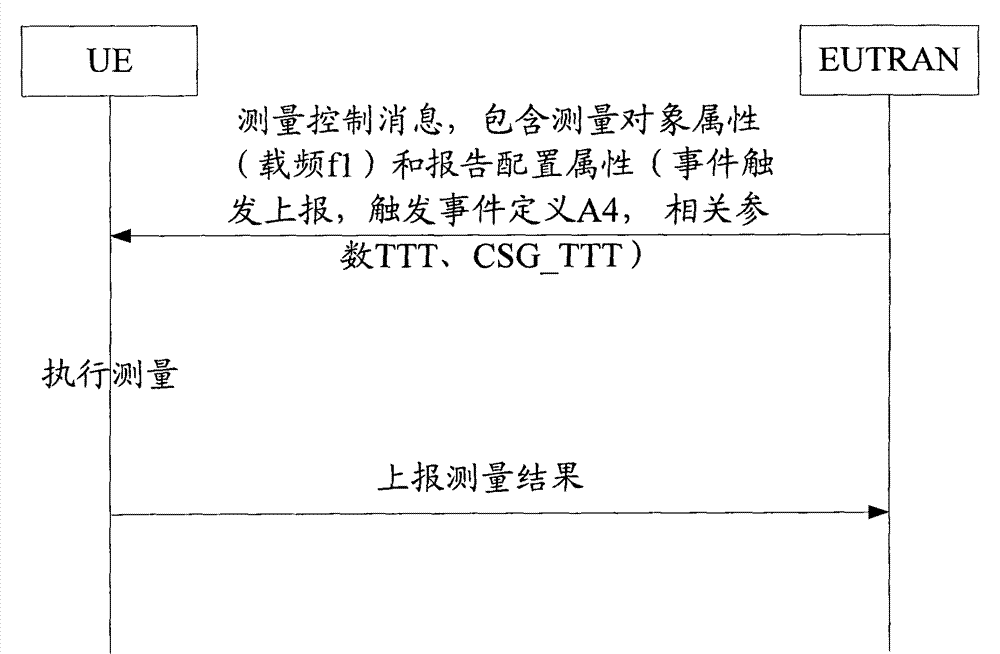
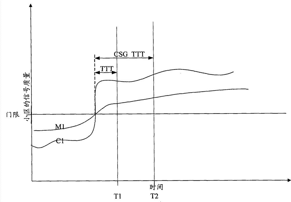
[0045] Embodiment 1 describes the situation of co-frequency adjacent cells, wherein the CSG cell adopts the CSG_TTT designated by the network side, the macro cell adopts the TTT designated by the network side, and the network side configures the same measurement task for the UE. Embodiment 2 describes the situation of inter-frequency adjacent cells, wherein the CSG cell uses the CSG_TTT specified by the network side, and instructs the UE to adjust the CSG_TTT according to the location and the coverage of the CSG cell, and the macro cell uses the TTT specified by the network side , the network side configures the same measurement task for the UE. Embodiment 3 describes the situation of neighboring cells of different systems, wherein, the CSG cell uses the CSG_TTT specified by the network side, and instructs the UE to adjust the CSG_TTT according to the signal quality of the CSG cell, and the macro cell uses the TTT specified by the network side, and the network side The same me...
Embodiment 2
[0051] Figure 3a is a flow chart of the measurement process according to Embodiment 2 of the present invention, such as Figure 3a As shown, the network sends a measurement control message to the UE, which includes a trigger event (A3) in which the measurement task is that the signal quality of the neighboring cell is better than that of the serving cell. The macro cell uses TTT and indicates the TTT offset TTT_offset, where TTT_offset>0, That is, the CSG cell adopts CSG_TTT=TTT+TTT_offset, and instructs the UE to adjust the CSG_TTT according to the location and the coverage of the CSG cell, and the carrier frequency of the measurement object is f2. After receiving the measurement task, the UE performs measurement on the measurement object.
[0052] Figure 3b is a schematic diagram of the measurement process according to Embodiment 2 of the present invention, such as Figure 3b As shown, when the time point T1 is reached, the signal quality of cell M1 is higher than that ...
Embodiment 3
[0057] Figure 4a is a flow chart of the measurement process according to Embodiment 3 of the present invention, such as Figure 4a As shown, the network sends a measurement control message to the UE, which includes a measurement task that the signal quality of the neighboring cell of the UMTS Terrestrial Radio Access Network (UTRAN for short) is better than the specified threshold (B1), and the macro cell uses TTT, the CSG cell uses CSG_TTT, the current CSG_TTT>TTT, and instructs the UE to adjust CSG_TTT according to the signal quality of the CSG cell is within the two cells with the best carrier frequency, and the carrier frequency of the measurement object is f3. After receiving the measurement task, the UE performs measurement on the measurement object.
[0058] Figure 4b is a schematic diagram of the measurement process according to Embodiment 3 of the present invention, such as Figure 4b As shown, when the time point T1 is reached, the signal quality of cells M1 and...
PUM
 Abstract
Description
Claims
Application Information
 - R&D
- Intellectual Property
- Life Sciences
- Materials
- Tech Scout
- Unparalleled Data Quality
- Higher Quality Content
- 60% Fewer Hallucinations
Browse by: Latest US Patents, China's latest patents, Technical Efficacy Thesaurus, Application Domain, Technology Topic, Popular Technical Reports.
© 2025 PatSnap. All rights reserved.Legal|Privacy policy|Modern Slavery Act Transparency Statement|Sitemap|About US| Contact US: help@patsnap.com


