Corn peeling device

A technology of corn and peeling rollers, which is applied in threshing equipment, agricultural machinery and implements, applications, etc., and can solve the problems of increased grain loss rate and reduced bract leaf peeling rate, etc.

Inactive Publication Date: 2010-11-03
LOVOL HEAVY IND
View PDF0 Cites 10 Cited by
  • Summary
  • Abstract
  • Description
  • Claims
  • Application Information

AI Technical Summary

Problems solved by technology

The defect that this structural form exists is: if the pressure feeding force of the pressure feeder is too large, although the peeling rate of the bract leaves is improved, it will cause the improve

Method used


Image

  • Corn peeling device
  • Corn peeling device
  • Corn peeling device

Examples


Embodiment Construction

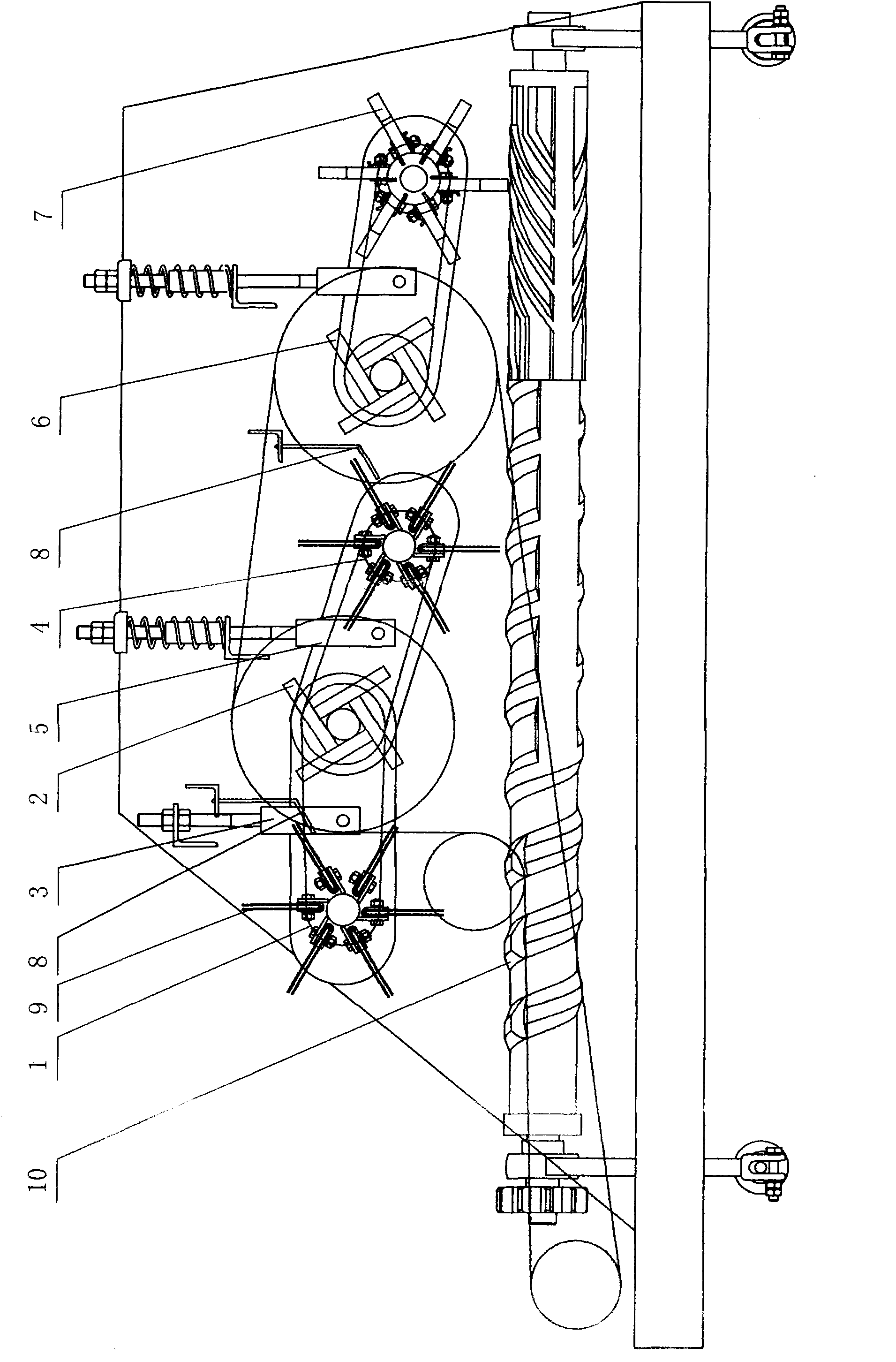
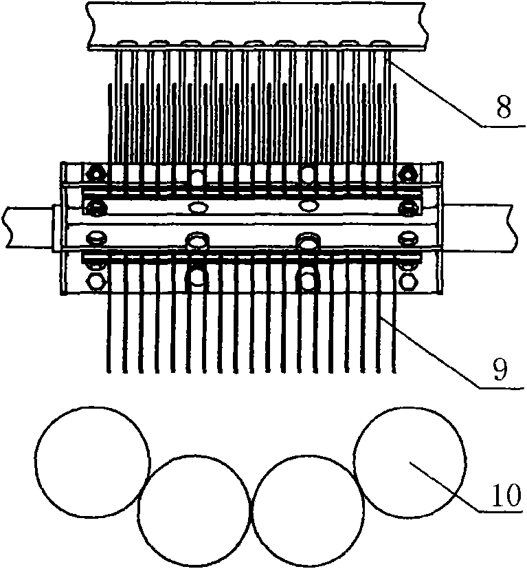
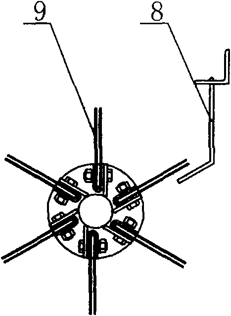
[0021] Such as figure 1 , figure 2 , image 3 , Figure 4 and Figure 5 Commonly shown, the corn peeling device comprises a frame; a peeling roller group consisting of peeling rollers 10, said peeling roller group comprising a pair of rigid rollers and a pair of rubber rollers, said rigid rollers and rubber rollers are arranged in parallel, at intervals and Arranged in a groove shape, the roller surface of the rigid roller is provided with spiral ribs, which can increase the ability to grasp the bracts and help to peel off the bracts. The peeling roller group is rotatably installed on the frame and Driven by the power device; the pressure feeder driven by the power device, the pressure feeder is rotatably installed on the frame, and the pressure feeder is at least two and arranged in sequence along the conveying direction of the fruit ears at the top of the peeling roller group Above, including the first pressure feeder 2 near the ear inlet end, the floating pressure feed...


PUM


Abstract

The invention discloses a corn peeling device. The device comprises a frame, a peeling roller group, pressure feeders and a husk combing device, wherein the peeling roller group is driven by a power device and rotatably arranged on the frame; the pressure feeders are driven by the power device and rotatably arranged on the frame; at least two groups of the pressure feeders are arranged above the peeling roller group in turn along a fruit cluster conveying direction; and the husk combing device is driven by the power device, arranged on the frame and positioned above the peeling roller group. Fruit clusters are combed, torn out and peeled, so that the peeling rate of the husk is enhanced remarkably; and peeling nails arranged along the axial direction of a rigid roller shaft in the conventional corn peeling device are eliminated, so that seed loss caused by the peeling nails is eliminated and the peeling rate of the husk and the seed loss rate can be balanced.

Description

technical field [0001] The invention relates to a corn peeling device for peeling off bract leaves of corn. Background technique [0002] The traditional corn peeling device generally adopts a groove-shaped arrangement of peeling rollers that are arranged in a staggered manner with rigid rollers and rubber rollers, and rotate in reverse. A number of peeling nails are arranged in the axial direction of the rigid rollers, and pressure rollers are arranged above the peeling rollers. The feeder, the fruit ears are fed by the pressure feeder and the friction of the peeling roller group, and the bracts are grabbed to realize the peeling function. The defect that this structural form exists is: if the pressure feeding force of the pressure feeder is too large, although the peeling rate of the bract leaves is improved, it will cause the improvement of the grain loss rate; if the pressure feeding force of the pressure feeder is too small, although It can reduce the loss rate of seed...

Claims


Application Information

Patent Timeline
IPC IPC(8): A01D45/02A01F11/06
Inventor 张明源李锐敏吴宗江谭树春宋涛韩克翠
Owner LOVOL HEAVY IND
Why Eureka
Try Eureka