Diaphragm structure used for pulse valve

A technology of pulse valve and diaphragm, which is applied to the separation of dispersed particles, chemical instruments and methods, and filtration of dispersed particles, etc. It can solve the problems of increasing the sealing leakage point of the diaphragm assembly, wear and tear, and the limitation of the use of pulse valves, etc., and achieves a simple structure , Wide range of application fields, low cost effect

Inactive Publication Date: 2010-11-03
上海袋式除尘配件有限公司
View PDF0 Cites 0 Cited by
  • Summary
  • Abstract
  • Description
  • Claims
  • Application Information

AI Technical Summary

Problems solved by technology

Limited by the characteristics of the rubber diaphragm, the stroke of its up and down movement is not large, causing the low-area channel it opens to become the throat area of ​​the compressed gas of the entire pulse valve from the air bag (gas distribution box) to the blowing pipe connected to the valve. Therefore, the blowing volume is limited, and at the same time, because the gasket and the rubber diaphragm are connected together, the sealing leakage point of the diaphragm assembly is increased, and because the diaphragm moves up and down, it is combined with the rubber diaphragm at the outer edge of the gasket It is easy to cause wear of the rubber diaphragm. In addition, due to the material characteristics of the rubber diaphragm, it cannot be used in many high-temperature and corrosive occasions, resulting in limitations in the use of pulse valves.

Method used


Image

  • Diaphragm structure used for pulse valve
  • Diaphragm structure used for pulse valve
  • Diaphragm structure used for pulse valve

Examples


Embodiment Construction

[0012] The present invention will be further described below in conjunction with accompanying drawing.

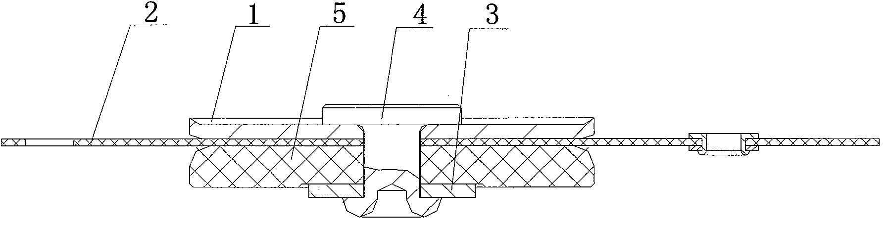
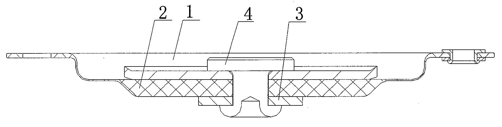
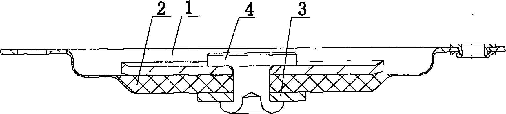
[0013] Such as figure 2 As shown, a diaphragm structure for a pulse valve includes a backing plate 1, a diaphragm 2, and a gasket 3 connected in sequence. The backing plate 1 is disc-shaped, and the front middle of the diaphragm 2 An annular protrusion 20 is provided for sealing, and the back side of the diaphragm 2 is attached to the peripheral wall and front side of the backing plate 1 to form a corrugated cross-section adapted to its stroke.

[0014] The diaphragm 2 is a polytetrafluoroethylene PTFE diaphragm; the backing plate 1, the diaphragm 2 and the gasket 3 are connected by rivets 4, or by threads.

[0015] The center of the diaphragm is used for the sealing of the valve body and seat of the pulse valve. The quality of the valve directly affects the performance of the pulse valve. The membrane assembly of the new structure makes the mechanical properties of the...


PUM


Abstract

The invention relates to a diaphragm structure used for a pulse valve, which comprises a base plate, a diaphragm and a gasket connected in turn, wherein the base plate has a disk shape; the middle part of the front of the diaphragm is provided with an annular protrusion used for sealing; and the back of the diaphragm is attached to the peripheral wall and the front of the base plate to form a corrugated section matched with the stroke of the diaphragm. Compared with the prior art, the diaphragm structure has simple structure and low cost, makes the diaphragm have more reasonable mechanical properties structurally, and can improve the usability and service life of the pulse valve; meanwhile, the adopted material has wider application range.

Description

technical field [0001] The invention relates to a diaphragm assembly, in particular to a diaphragm structure for a pulse valve. Background technique [0002] The pulse valve is mainly used in the bag filter, which uses the change of gas pressure to blow the compressed gas in the air bag (gas distribution box) into the air chamber of the bag filter, and makes the solids attached to the filter material The dust is separated to achieve the purpose of dust removal or collection, which is a key accessory of the bag filter. It is widely used in the field of dust control and collection in various industries. [0003] Such as figure 1 As shown, the customary diaphragm assembly is composed of rubber diaphragm 2, gasket 5, backing plate 1, rivet 4, gasket 3, etc., rubber diaphragm 2, gasket 5, backing plate 3, and gasket 1 are composed of rivets 4 riveted together. Limited by the characteristics of the rubber diaphragm, the stroke of its up and down movement is not large, causing ...

Claims


Application Information

Patent Timeline
Patent Type & Authority Applications(China)
IPC IPC(8): B01D46/04
Inventor 劳以诺黄河叶桐萃
Owner 上海袋式除尘配件有限公司
Why Eureka
Try Eureka