Ejector mechanism and injection mold therewith

A technology of ejection mechanism and injection mold, which is applied in the field of injection mold and its ejection mechanism, which can solve the problems of damaged barb or ball head structure, high defect rate of products, etc., and achieve the effect of high processing efficiency

Inactive Publication Date: 2010-11-03
SHENGMEI PRECISION INDAL KUSN
View PDF3 Cites 15 Cited by
  • Summary
  • Abstract
  • Description
  • Claims
  • Application Information

AI Technical Summary

Problems solved by technology

[0002] When processing some products with a ball head or barb structure by injection molding, male mold inserts and thimbles are required. The ball head structure or barb structure is formed by the thimble. After the injection molding is completed, the product needs to be separated from the mold. , the existing technology requires two ejections, which are completed by the first ejection plate, the s...

Method used


Image

  • Ejector mechanism and injection mold therewith
  • Ejector mechanism and injection mold therewith
  • Ejector mechanism and injection mold therewith

Examples


Embodiment Construction

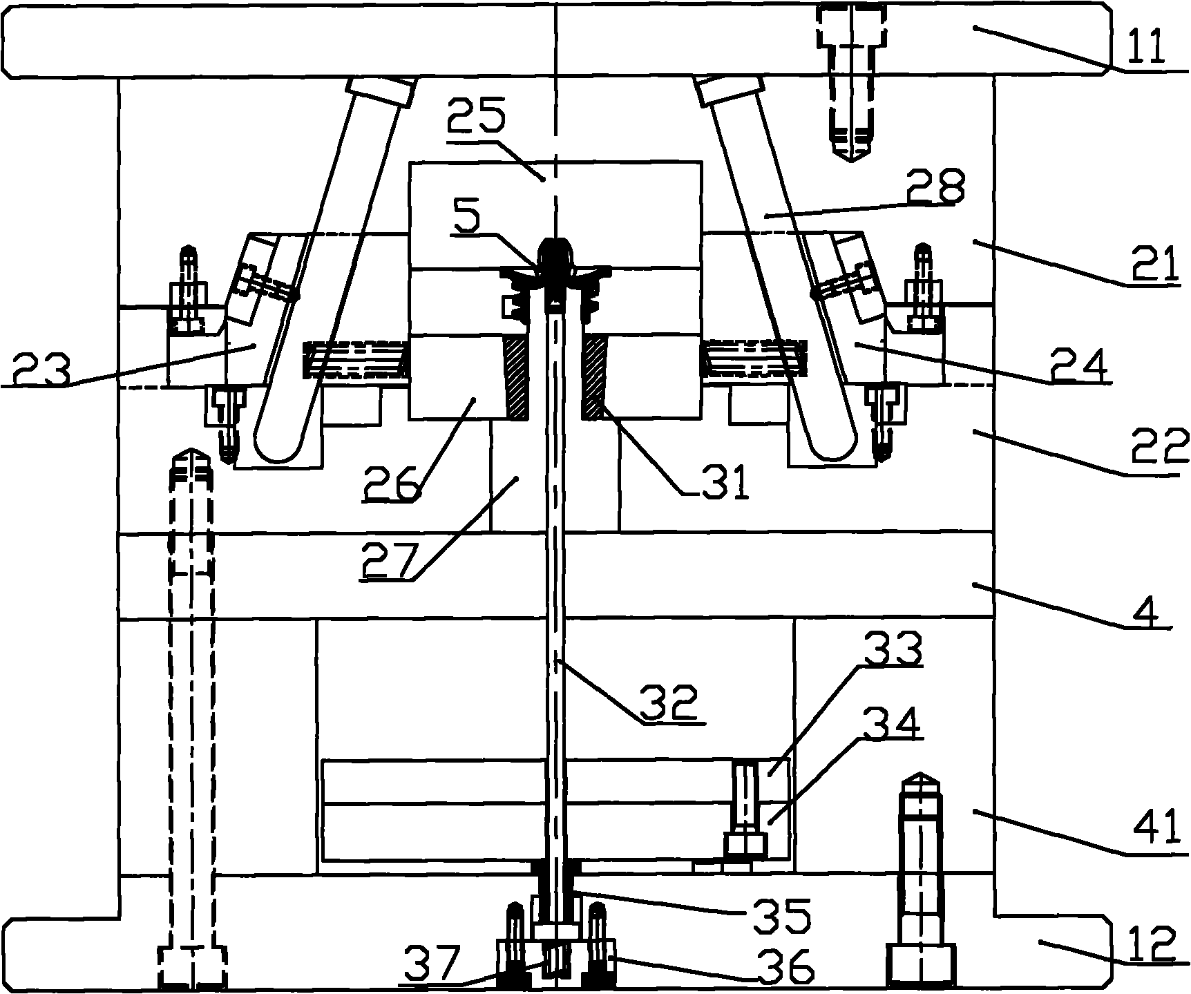
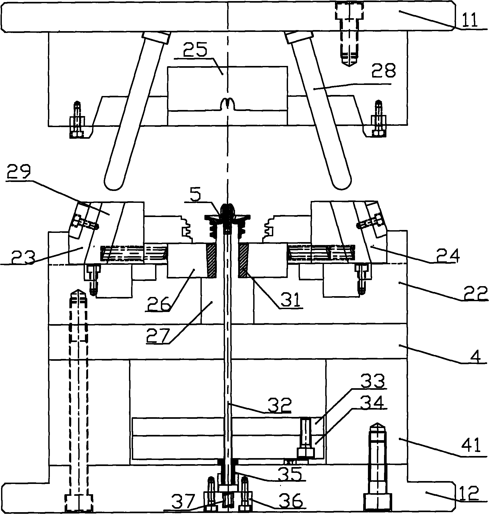
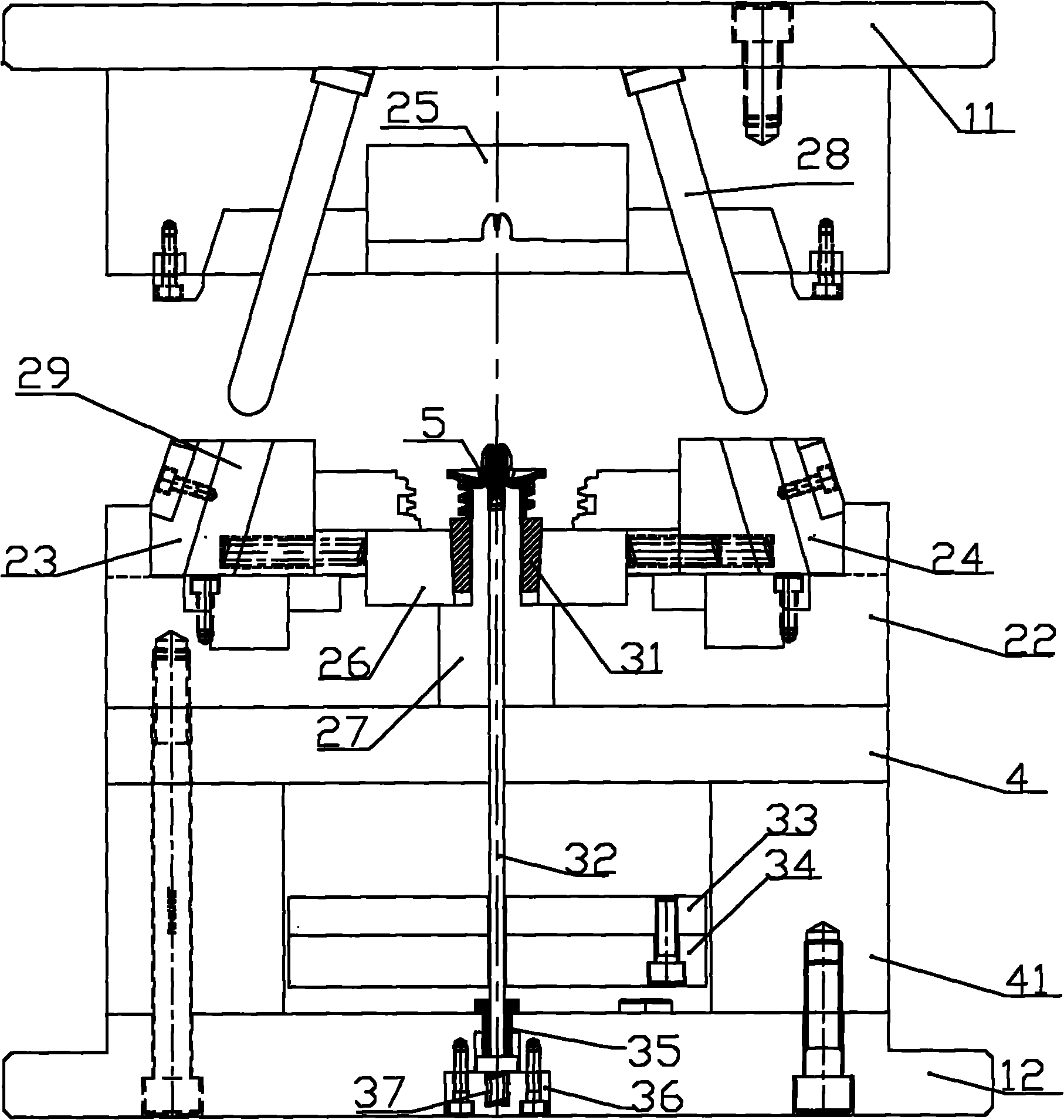
[0013] The present invention will be further described below in conjunction with the accompanying drawings and embodiments. figure 1 Corresponds to the upper and lower positional relationships in .

[0014] An injection mold with an ejection mechanism, which includes a front plate 11, a rear plate 12, a master template 21 fixedly arranged on the front plate 11 and a female mold core 25, a pair of mold cores fixedly arranged on the back plate 12 Pillow board 41, bearing plate 4 arranged above a pair of pillow boards 41, male template 22 fixedly arranged on said bearing board 4 and male mold kernel 26, slidably arranged on said male template 22 The left slider 23 and the right slider 24 , the ejection mechanism, and the upper ejection plate 33 and the lower ejection plate 34 are also slidably arranged between the rear plate 12 and the bearing plate 4 .

[0015] The male die insert 27 is fixedly arranged on the male template 22, the male die insert 26 passes through the male die...


PUM


Abstract

The invention relates to an ejector mechanism and an injection mold therewith. The ejector mechanism comprises a floating thimble and an ejector block, wherein the lower end part of the floating thimble is elastically connected with a rear plate, the ejector block is positioned below a mold cavity and can be slidably sleeved on the upper part of a male mold along the longitudinal direction; and the floating thimble penetrating a male mold core insert and the upper end part of the floating thimble extends into the mold cavity, the lower end part of the floating thimble is fixedly provided with a pulling-back sleeve, and a spring providing a downwards restoring force for the floating thimble is arranged between the pulling-back sleeve and the rear plate. The ejector block is connected with a drive part, the ejector block drives an injection product and the floating thimble to upwards move when the mold is opened until the periphery of the injection product is provided with an extending space, and the floating thimble is pulled out; the plasticity of the injection product is fully utilized, and the damage of the injection product caused by forced demolding is avoided.

Description

technical field [0001] The invention relates to an injection mold and an ejection mechanism thereof. Background technique [0002] When processing some products with a ball head or barb structure by injection molding, male mold inserts and thimbles are required. The ball head structure or barb structure is formed by the thimble. After the injection molding is completed, the product needs to be separated from the mold. , the existing technology requires two ejections, which are completed by the first ejection plate, the second ejection plate and the ejector pin, the first ejection: the injection molded product is ejected together with the second ejection plate, and the second ejection, The second ejection plate does not move, and the first ejection plate and ejector pin move, forcing the end of the ejector pin to be pulled out. This process often damages the barb or ball head structure, resulting in a high defect rate of products. Contents of the invention [0003] The obj...

Claims


Application Information

Patent Timeline
IPC IPC(8): B29C45/40B29C45/26
Inventor 孔斌
Owner SHENGMEI PRECISION INDAL KUSN
Why Eureka
Try Eureka