Pipe expanding equipment

A kind of equipment and tube expansion technology, which is applied in the field of tube expansion equipment, can solve the problems that the effective expansion of tube sheets cannot be satisfied, and the simultaneous expansion of multiple pipe fittings on two tube sheets cannot be realized, so as to reduce the cost of expansion joints , Simple structure, high expansion efficiency

Active Publication Date: 2012-07-04
ZHEJIANG DAYANG SEWING MACHINE
View PDF1 Cites 0 Cited by
  • Summary
  • Abstract
  • Description
  • Claims
  • Application Information

AI Technical Summary

Problems solved by technology

[0004] The tube expander disclosed in this patent solves the above-mentioned problems to a certain extent. However, the tube expander can only expand multiple tubes on one tube sheet at the same time, and cannot simultaneously expand multiple tubes. On the two tube sheets, at the same time, the effective expansion of the tube sheets cannot be satisfied, which reduces the work efficiency and increases the cost of expansion joints

Method used


Image

  • Pipe expanding equipment
  • Pipe expanding equipment
  • Pipe expanding equipment

Examples


Embodiment 1

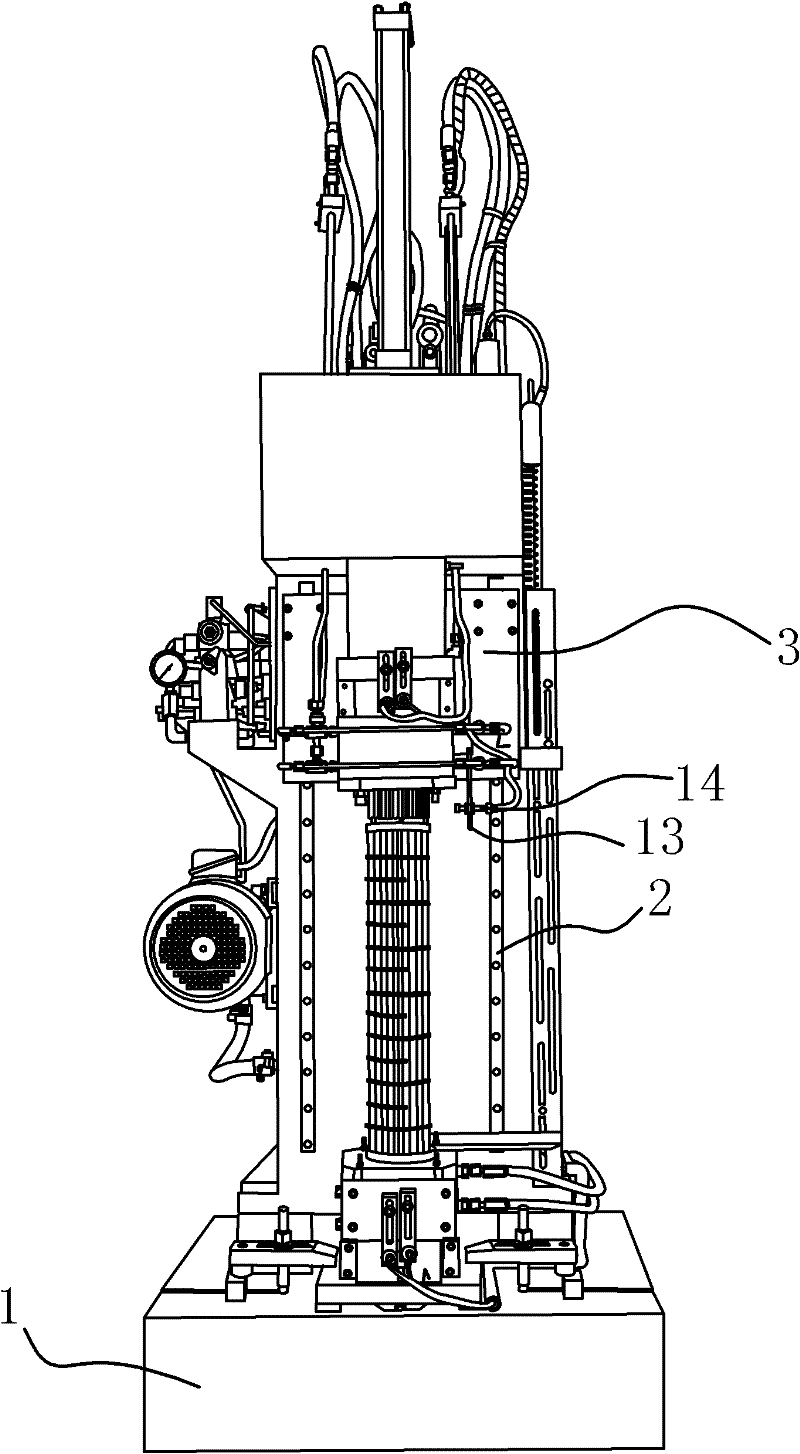
[0042] Such as figure 1 As shown, a tube expansion device is mainly divided into two types: vertical and horizontal. In the first embodiment, the tube expansion device is vertical, including a base 1, on which two The tube expander with the same structure is oppositely arranged, and the lower tube expander is fixed on the machine base 1 . On the machine base 1, a guide rail 2 is provided along the line direction of the two expansion devices. The guide rail 2 is provided with a carriage 3 that can slide along the guide rail 2. plate 3.

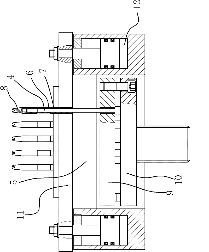
[0043] Such as figure 2 As shown, there are several expansion rods 4 with the same number and one-to-one correspondence on the two expansion devices. The expansion device also includes a support plate 5 and a power mechanism. 5 Clearance fit, one end of the expansion rod 4 protrudes from the support plate 5 and an expansion joint structure is provided at this end, the other end of the expansion rod 4 is connected to the power mechanism on t...

Embodiment 2

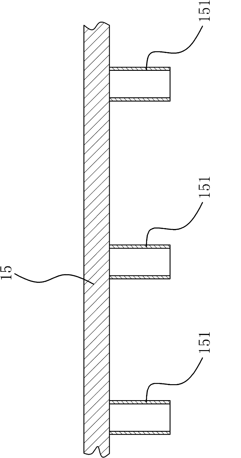
[0049] The content in the second embodiment is roughly the same as that in the first embodiment, the difference is that the tube expansion equipment in the first embodiment includes an upper tube expansion device and a lower tube expansion device, while the tube expansion device in the second embodiment The tube expanding device includes a tube expanding device and a positioning frame 15 for positioning the tube.

[0050] Specifically, the positioning frame 15 is fixed on the carriage 3, such as image 3 As shown, the positioning frame 15 has a number of positioning rods 151 which are the same in number as the expansion rods 4 and whose positions correspond to one-to-one. The positioning rods 151 are used to position the pipe fittings. The structure is simple and the positioning effect is good.

[0051]The tube expansion equipment in the second embodiment is used to expand several tube fittings on a tube sheet. The working principle of the tube expansion equipment is as follow...


PUM


Abstract

The invention provides pipe expanding equipment and belongs to the technical field of machinery. The pipe expansion equipment solves the technical problems of low expansion connection effect and efficiency and high cost of the conventional pipe expansion equipment. The pipe expansion equipment comprises a machine base on which one or two pipe expansion devices can be arranged. Two pipe expansion devices are arranged to expand and connect the two ends of a pipe at the same time; the two pipe expansion devices are arranged above and below the machine base symmetrically; the lower pipe expansiondevice is fixed on the machine base; guide rails are arranged on the machine base; a planker is arranged on the guide rails; the upper pipe expansion device is fixed on the planker; and the two pipe expansion devices both have a plurality of expansion rods which can expand and connect the pipe to a pipe plate. When a single pipe expansion device is arranged to expand and connect one end of the pipe, a positioning frame is arranged at the position of the other pipe expansion device to fixe and position the pipe arranged on the pipe expansion device. The equipment can expand and connect two or one end of the pipe and has the advantages of simple operation, convenient charging, good expansion and connection effect and high expansion and connection efficiency.

Description

technical field [0001] The invention belongs to the technical field of machinery, and relates to a tube expansion device, in particular to a tube expansion device capable of expanding a plurality of tube fittings on a tube plate. Background technique [0002] In the process of modern machining, it is necessary to expand multiple tube fittings on one tube sheet or two tube sheets. For example, in the production process of condensers, it is necessary to connect multiple tube fittings on , The next two tube plates. Since the cooling medium of the condenser flows in the tube fittings, and the medium for heat exchange flows between the upper tube sheet and the lower tube sheet, in order to prevent the leakage of the medium, it is necessary to ensure the tightness between the tube fittings and the upper and lower tube sheets . In order to solve this problem, a kind of expansion equipment is generally used to connect the pipe fittings to the upper and lower tube plates in the for...

Claims


Application Information

Patent Timeline
IPC IPC(8): B21D39/08B21D53/08
Inventor 曹忠泉
Owner ZHEJIANG DAYANG SEWING MACHINE
Why Eureka
Try Eureka