Working solution tank of ultrafine electrical discharge machine

A working liquid tank and electric discharge machining technology, applied in the field of mechanical processing, can solve the problems of working oil circulation, overflow or poor oil speed adjustment, inconvenient processing operations, etc., and achieve the effect of convenient operation

Inactive Publication Date: 2010-11-10
WUXI MICRO RES
View PDF5 Cites 1 Cited by
  • Summary
  • Abstract
  • Description
  • Claims
  • Application Information

AI Technical Summary

Problems solved by technology

At present, the working fluid tank of the existing electrical discharge machining machine tool has poor performance in regulating the circulation, overflow or oil feeding speed of the working oil, and the processing operation is inconvenient

Method used


Image

  • Working solution tank of ultrafine electrical discharge machine
  • Working solution tank of ultrafine electrical discharge machine
  • Working solution tank of ultrafine electrical discharge machine

Examples


Embodiment Construction

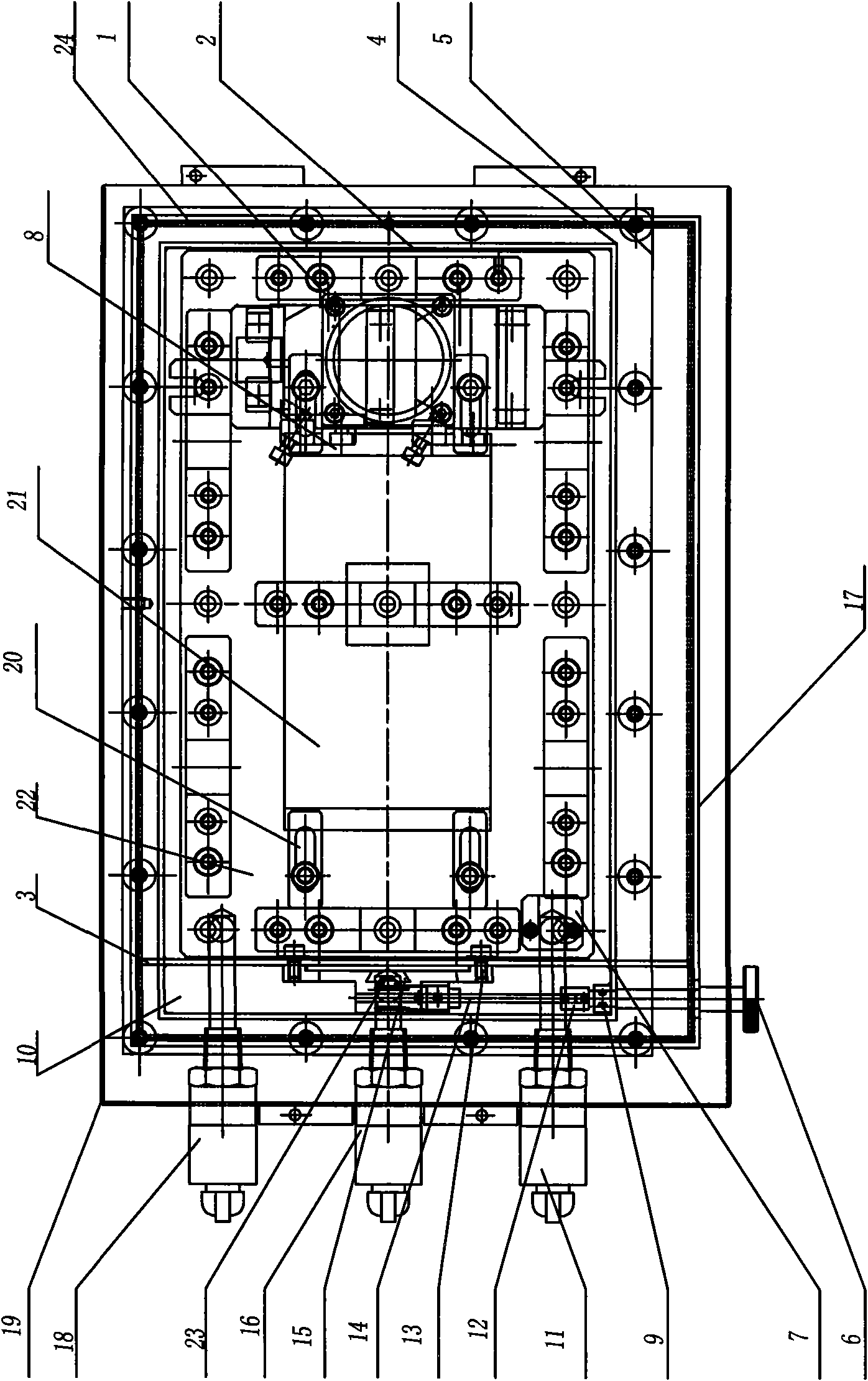
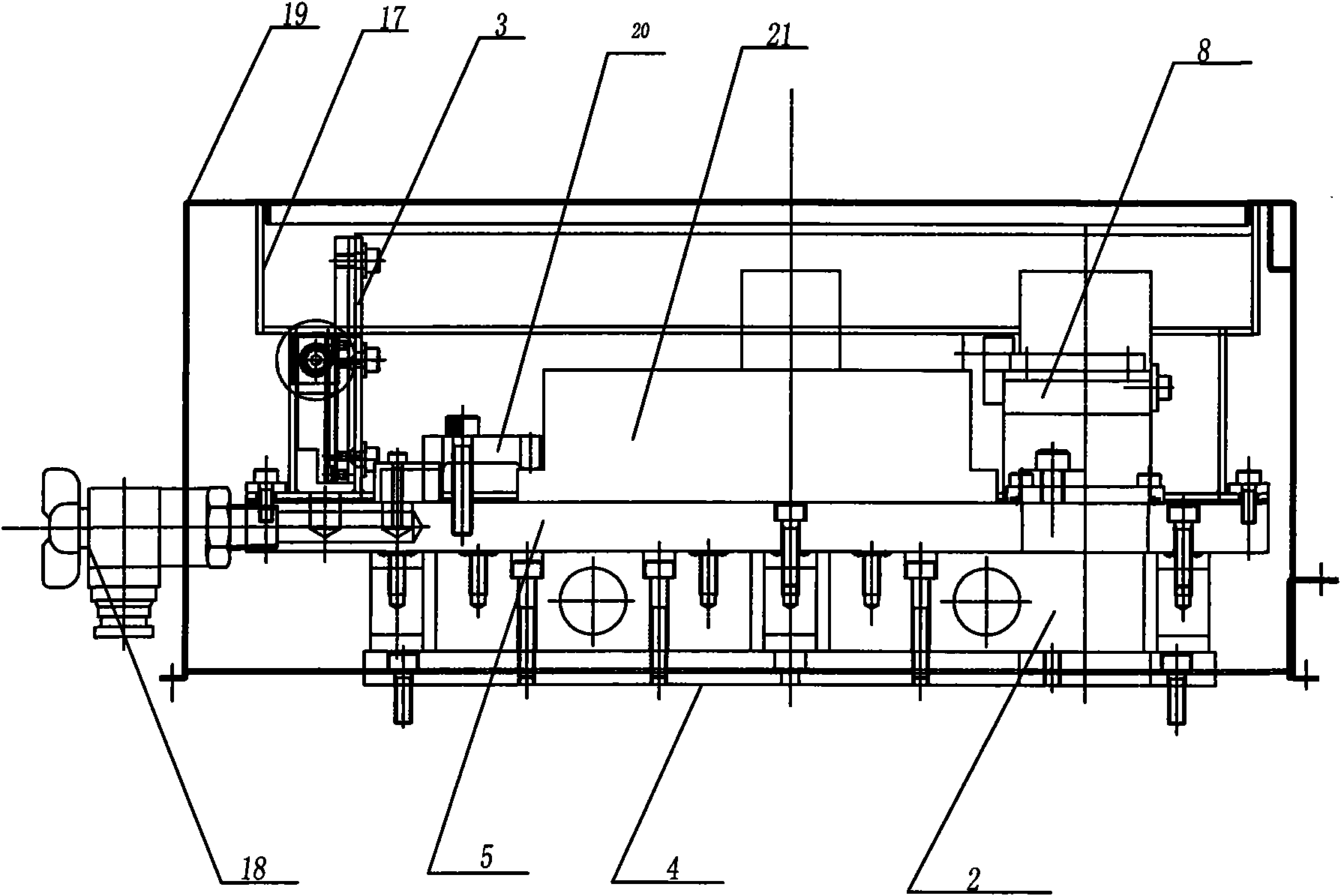
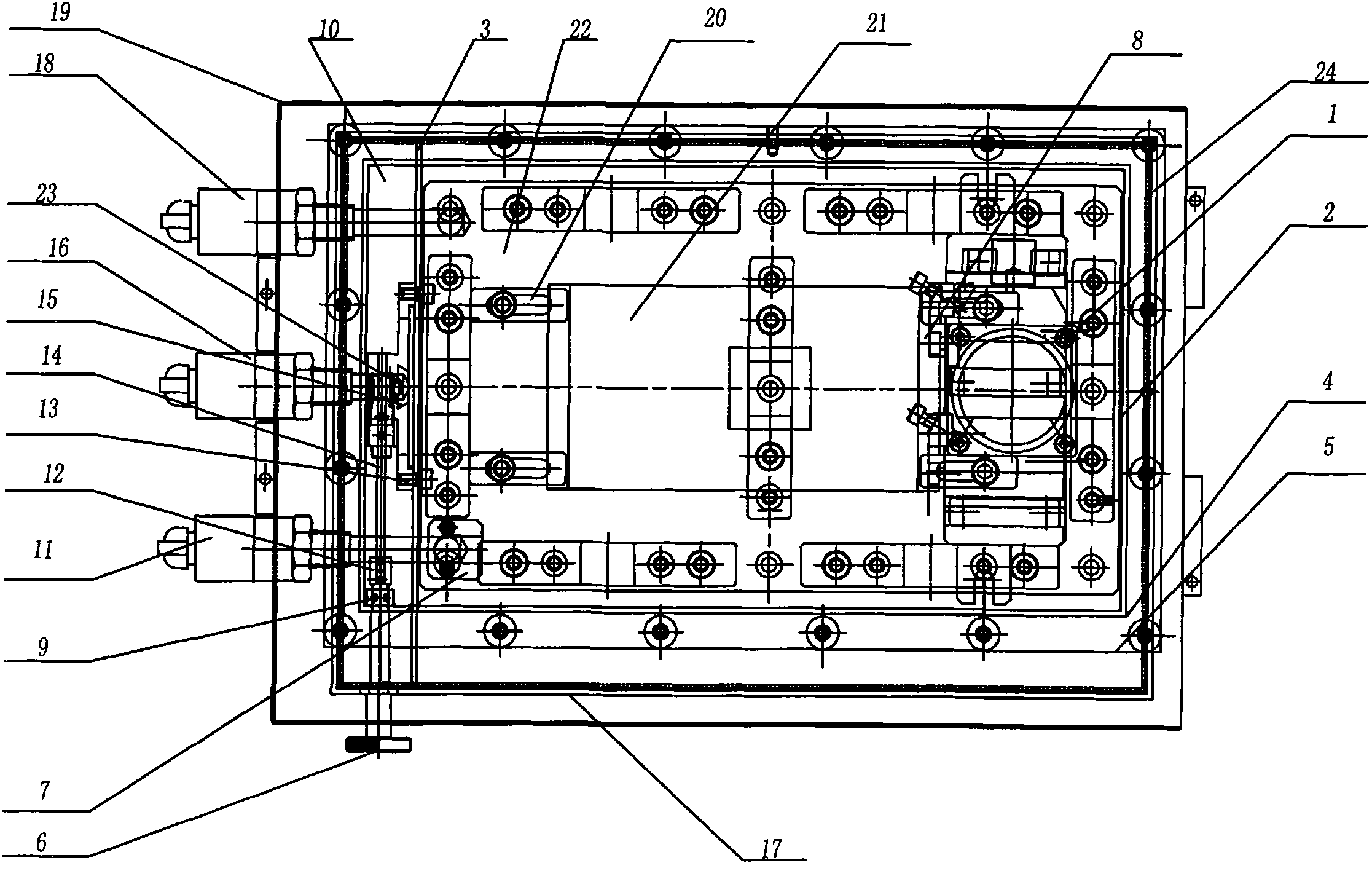
[0009] As shown in the figure: the present invention includes an oil outlet 1, a middle plate 2, a middle baffle 3, a lower bottom plate 4, an upper bottom plate 5, an adjustment handle 6, an oil inlet 7, an anti-copy block 8, a sealing ring 9, an overflow Area 10, oil inlet valve 11, coupling 12, fastening bolt 13, transmission shaft 14, screw rod 15, overflow valve 16, side plate 17, oil return valve 18, housing 19, fixture positioning block 20, Workpiece fixture 21 , processing area 22 , cover plate 23 and end side plate 24 .

[0010] Such as figure 1 and figure 2 As shown: the bottom of the housing 19 is provided with an upper base plate 5, and a lower base plate 4 is arranged below the upper base plate 5; an intermediate plate 2 is provided between the upper base plate 5 and the lower base plate 4, and the intermediate plate 2 is used for Adjust the height between the lower base plate 4 and the upper base plate 5. When in use, the lower base plate 4 is connected with ...


PUM


Abstract

The invention relates to a working solution tank of an ultrafine electrical discharge machine. According to the technical scheme provided by the invention, the working solution tank of an ultrafine electrical discharge machine comprises a shell, wherein the bottom of the shell is provided with an upper base plate. The working solution tank is characterized in that side plates and an end plates which are fixedly connected are arranged on the upper base plate to form the working solution tank; a middle baffle plate is also arranged on the upper base plate and fixedly connected with the side plates at both ends and divides the working solution tank into an overflow area and a machining area; one end of the upper base plate is provided with an oil inlet valve, an overflow valve and an oil return valve; the end parts of the oil inlet valve and the oil return valve are both positioned in the machining area, and the end part of the overflow valve is positioned in the overflow area; the end part of the side plate, which corresponds to the adjacent oil inlet valve is provided with an adjusting handle; a screw rod is arranged on the adjusting handle; a cover plate is arranged on the screw rod; and the cover plate is positioned above an inlet of the overflow valve. The invention has simple structure, good adjusting performance, convenient use, safety and reliability.

Description

technical field [0001] The invention relates to a working fluid tank, in particular to a working fluid tank of an ultra-fine electrical discharge machining machine tool, belonging to the technical field of mechanical processing. Background technique [0002] The principle of EDM is based on the electro-corrosion phenomenon during the pulsed spark discharge between the tool and the workpiece (positive and negative electrodes) to remove excess metal to achieve the predetermined processing requirements for the size, shape and surface quality of the parts. The pulsed spark discharge forms a conductive circuit through the working fluid of the machine tool. In actual processing, the circulation of working oil, overflow device, oil feeding speed, etc. play a very important role in processing efficiency. At present, the working liquid tank of the existing electrical discharge machining machine tool has poor performance in regulating the circulation, overflow or oil feeding speed of...

Claims


Application Information

Patent Timeline
Patent Type & Authority Applications(China)
IPC IPC(8): B23H1/10
Inventor 谈渊智宋曼栾纪杰
Owner WUXI MICRO RES
Why Eureka
Try Eureka