Freezing device

A freezing device and anti-icing technology, which is used in household refrigeration devices, coolers, lighting and heating equipment, etc., to achieve the effects of reducing health hazards, stable structure and good cleaning effect.

Active Publication Date: 2012-10-03
SIFANG TECH GRP CO LTD
View PDF0 Cites 2 Cited by
  • Summary
  • Abstract
  • Description
  • Claims
  • Application Information

AI Technical Summary

Problems solved by technology

[0006] The purpose of this utility model is to overcome the above shortcomings and provide a technical solution for a freezing device. The horizontal centrifugal fan of the device is installed under the top blowing evaporator as much as possible, so that the space inside the device for manual cleaning is spacious. The device has an anti-icing bracket and a steam heating windshield device under the frozen conveyor belt to eliminate the phenomenon of ice under the conveyor belt. There is a water tank at the bottom of the feeding mechanism of the device. The low-temperature conveyor belt is cleaned after the water tank is heated up. To save water, the tension shaft roller of the second section of the circulating conveyor belt of the device is located in the heat insulation box near the discharge mechanism, which is easy to operate

Method used


Image

  • Freezing device
  • Freezing device
  • Freezing device

Examples


Embodiment 1

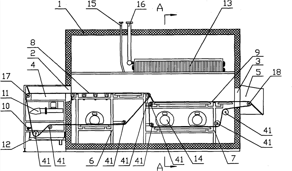
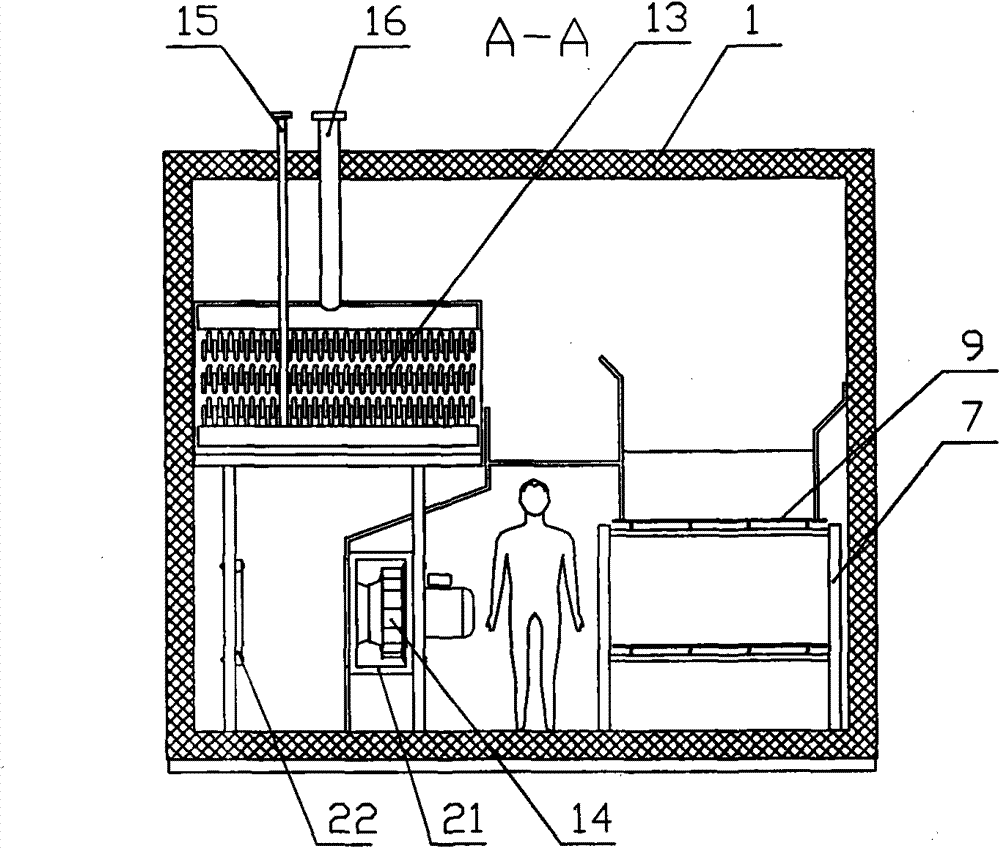
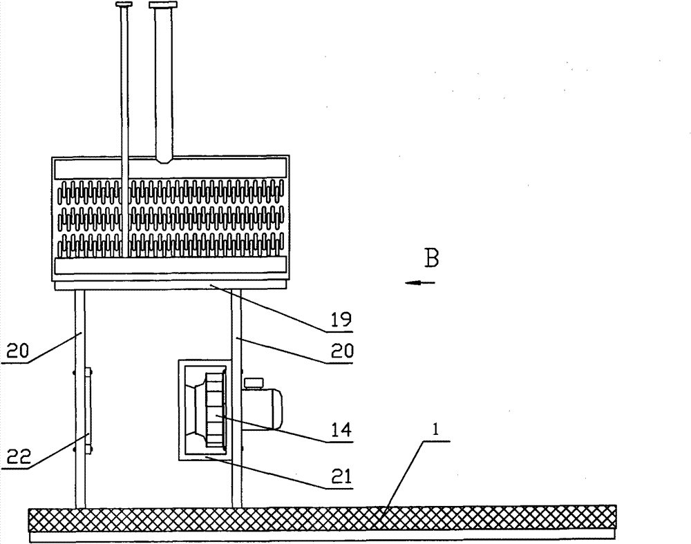
[0033] Freezing device (see figure 1 , figure 2 ) Including the insulated box 1, the feeding mechanism 4 and the discharging mechanism 5 respectively placed in the inlet 2 and outlet 3 of the insulated box 1, and the feeding conveyor belt frame 6 installed in the insulated box 1. And the discharge conveyor belt frame 7, respectively installed on the infeed conveyor belt frame 6 and the discharge conveyor belt frame 7, the first section of the circulating conveyor belt 8 and the second section of the circulating conveyor belt 9, located in the feeding mechanism 4 The flushing device 10, the blowing device 11, and the water collecting pan 12 below are located in the heat-insulating box 1 and are a cooler composed of a top blowing evaporator 13 and a horizontal centrifugal fan 14. The liquid supply pipe 15 and the air return pipe 16 of the top blowing evaporator 13 are respectively connected to the refrigeration unit. The drive shaft roller 17 of the first section of the circulati...

Embodiment 2

[0035] The difference from Example 1 is: the insulating box 1 has an anti-icing bracket 23 (see Figure 5 , Image 6 , Figure 7 ), the two ends of the anti-icing bracket 23 are fixedly connected with the mounting plate 24 and the feeding conveyor belt frame 6. The upper plane 25 and the two side faces 26 of the anti-icing bracket 23 are basically made of polytetrafluoroethylene material to form a polytetrafluoroethylene supporting surface. There is a PTFE material between the upper plane 25 and the two side faces 26. Wear-resistant strips 27 of ultra-high molecular weight polyethylene material. 28 is a mounting screw, 29 is a mounting screw, and 30 is a mounting nut. The polytetrafluoroethylene sleeve 31 is connected to the mounting screw 29 with a split pin 32. There is at least one anti-icing bracket 23 under the first stage of the circulating conveyor belt 8, and multiple anti-icing brackets 23 may also be provided.

Embodiment 3

[0037] The difference from embodiment 1 or 2 is: the first section of the circulating conveyor belt 8 at the inlet 2 of the insulated box 1 has a steam heating windshield device 33 (see Figure 8 , Picture 9 , Picture 10 ), the wind deflector 34 of the steam-heated wind deflector 33 is fixedly connected to the insulated box 1 5 The upper plane 35 of the air heating windshield device 33 and the lower edge of the polytetrafluoroethylene side surface 26 of the anti-icing bracket 23 meet and incline the outside of the insulated box 1 downward. The wind deflector 34 and the upper plane 35 are fixed on the heating pipe 37 with a heat conducting plate 36. A steam pipe 38 is inserted into the heating pipe 37. There is a steam return pipe 39 at the bottom of the heating pipe 37. The steam passes into the steam pipe 38 and enters the heating pipe 37. It then flows out through the return steam pipe 39.


PUM


Abstract

The invention discloses a freezing device comprising a heat insulating tank body, a feeding mechanism, a discharging mechanism, two conveying belts, a conveying belt stand, a top-blowing evaporator and a horizontal type centrifugal fan, wherein the feeding mechanism and a discharging mechanism are respectively arranged on a feed port and a discharge port of the heat insulating tank body, and the two conveying belts, the conveying belt stand, the top-blowing evaporator and the horizontal type centrifugal fan are arranged in the heat insulating tank body; a supporting rod is arranged below a cross beam of a support of the top-blowing evaporator, the supporting rod, the cross beam and the heat insulating tank body are fixedly connected to form a stressed member, and a frame-shaped fan stand is fixedly arranged on the supporting rod of the stressed member to form a stressed frame; an anti-icing bracket is arranged below the frozen conveying belt, a steam heating wind-shielding device is arranged below the conveying belt at the feeding port, the bottom of the feeding mechanism is provided with a conveying belt heating-up water tank, and a conveying belt tensioning shaft roll is arranged at the discharging mechanism. The invention has the advantages of stable structure, safe installation process of the evaporator and convenient use and also has the advantages of eliminating the phenomenon of icing under the conveying belts, prolonging the continuous running time of the freezing device and improving efficiency; and besides, because the low-temperature conveying belt is washed after immersed in the water tank and heated up, less water consumption and good cleaning effect are achieved.

Description

Technical field: [0001] The invention relates to a freezing equipment, in particular to a two-stage circulating conveyor belt type freezing device. Background technique: [0002] In the existing two-stage circulating conveyor belt type freezing device, the top blower evaporator and the horizontal centrifugal fan used for circulating heat exchange occupy a large space inside the freezing device, which makes the space for manual cleaning inside the device during the non-production process. narrow. [0003] In the existing two-stage circulating conveyor belt type freezing device, the moisture wrapped by the frozen product enters the freezing device and freezes on the supporting rail below the conveyor belt and gradually thickens to form pack ice. The serious pack ice phenomenon causes the conveyor belt damaged. [0004] In the existing two-stage circulating conveyor belt type freezing device, the low-temperature conveyor belt at the bottom of the feeding mechanism and driven out of th...

Claims


Application Information

Patent Timeline
Patent Type & Authority Patents(China)
IPC IPC(8): F25D13/06F25D21/04
Inventor 钱洪周鸣惠杨晓燕
Owner SIFANG TECH GRP CO LTD
Why Eureka
Try Eureka