

Scraper
A scraper and scraper technology, which can be applied to household appliances, cleaning methods and utensils, cleaning methods using tools, etc., can solve the problems of decreased shaving feeling, damage to objects, etc., and achieve the effect that the shaving feeling is not easy to deteriorate.
- Summary
- Abstract
- Description
- Claims
- Application Information
AI Technical Summary
Problems solved by technology
Method used
Image

Examples
no. 1 approach
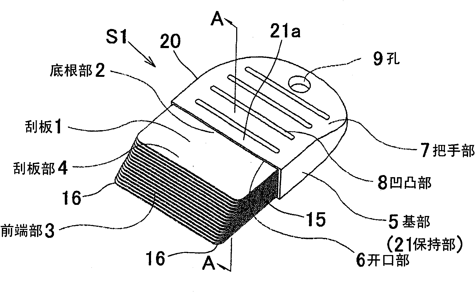
[0070] Figure 1~3 It is a figure explaining the scraper S1 which concerns on 1st Embodiment of this invention. The structure of this scraper S1 is as follows.
[0071] (1) The squeegee 1 composed of a plurality of square flexible resin plates is stacked in such a way that the respective widths are uniform and the length changes in a step shape, and one end is uniform to form the bottom root 2 and the other end is a stepped front end. 3. Form the scraper part 4 as a whole.
[0072] (2) Both ends of the front end portion 3 of the squeegee 1 have rounded corners.
[0073] (3) The base 5 is made of flat resin or wood. An opening 6 facing forward is provided on one end vertically of the base 5 , and the other end is a handle 7 .
[0074] (4) On the surface of the handle part 7, the uneven part 8 for anti-slip is provided, and the hole 9 for hanging is provided.
[0075] (5) The base portion 2 of the scraper portion 4 is inserted into the opening portion 6 and fixed by bonding....
no. 2 approach
[0092] Figure 4 It is a figure explaining the scraper S2 which concerns on 2nd Embodiment of this invention. The structure of this scraper S2 is as follows.
[0093] (1) The squeegee 1 composed of a plurality of square flexible resin plates is stacked in such a way that the respective widths are uniform and the length changes in a step shape, and one end is uniform to form the bottom root 2 and the other end is a stepped front end. 3. Form the scraper part 4 as a whole.
[0094] (2) Both ends of the front end portion 3 of the squeegee 1 have rounded corners.
[0095] (3) The base 5 is made of flat resin or wood. An opening 6 facing forward is provided on one end vertically of the base 5 , and the other end is a handle 7 .
[0096] (4) On the surface of the handle part 7, the anti-slip uneven part 8 is provided, and the front end part of the handle part 7 is provided with the hole 9 for hanging.
[0097] (5) The base portion 2 of the scraper portion 4 is inserted into the ...
no. 3 approach
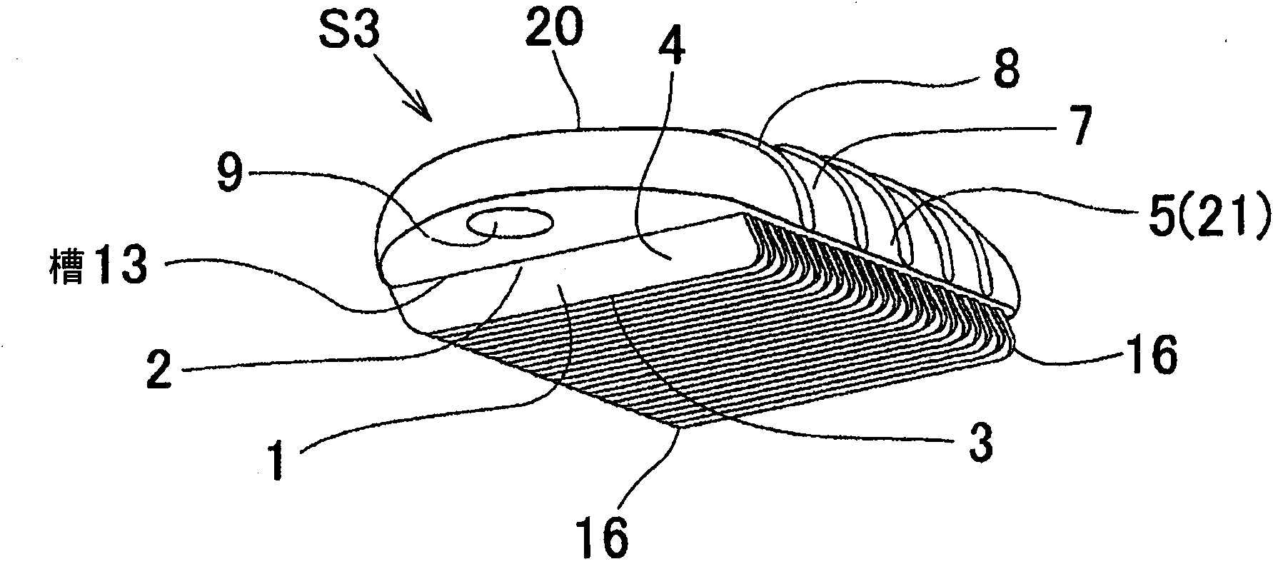
[0102] Figure 5-7 It is a figure explaining the scraper S3 which concerns on 3rd Embodiment of this invention. The structure of this scraper S3 is as follows.
[0103] (1) One end of the squeegee 1 made of a horizontally long rectangular flexible resin plate is the base 2, and the other end is the front end 3, and both ends of the front end 3 have rounded corners.
[0104] (2) On the lower surface of the base 5 made of flat resin or wood, a plurality of grooves 13 are provided intermittently and at equal intervals towards the obliquely upward direction of the base 5 .
[0105] (3) The base portion 2 of the scraper 1 is inserted into each groove 13 and fixed by bonding.
[0106] (4) The upper surface and the side surface of the base 5 are handles 7, on which an anti-slip unevenness 8 is provided, and marks 14 such as arrows indicating the direction of the front end of the scraper 1 are shown. One end portion is provided with the hole 9 that hangs usefulness.
[0107] The s...
PUM
 Abstract
Description
Claims
Application Information