Compact injection unit with injectors opening inwards

A technology of injection devices and injectors, applied in fuel injection devices, low-pressure fuel injection, charging systems, etc., can solve the problems of complex structure and large structural space, and achieve the effect of compact structure and simple cost

Active Publication Date: 2014-10-29
ROBERT BOSCH GMBH
View PDF5 Cites 0 Cited by
  • Summary
  • Abstract
  • Description
  • Claims
  • Application Information

AI Technical Summary

Problems solved by technology

However, the structure is relatively complex and the device occupies a large construction space

Method used


Image

  • Compact injection unit with injectors opening inwards
  • Compact injection unit with injectors opening inwards
  • Compact injection unit with injectors opening inwards

Examples


Embodiment Construction

[0018] Refer to the following Figures 1 to 4 A small engine 1 having an injection device according to a first embodiment of the present invention will be described in detail.

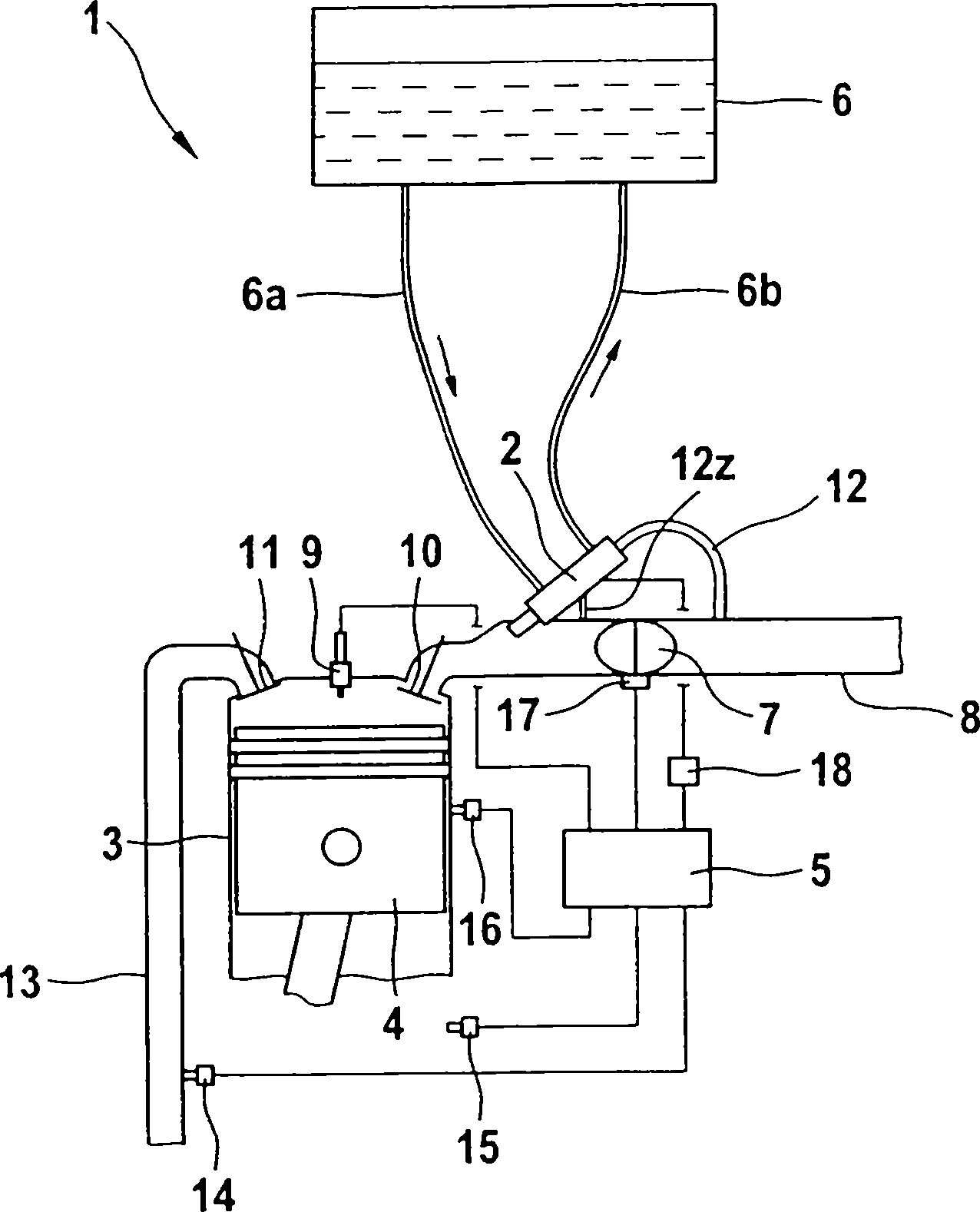
[0019] figure 1 The structure of the small engine 1 configured as a single-cylinder engine is schematically shown. The small engine 1 comprises a cylinder 3 , a piston 4 reciprocable inside it, a control unit 5 and a tank 6 . Tank 6 is connected to injection unit 2 via a fuel feed line 6a. A fuel return line 6b returns from the injection assembly 2 to the tank 6 . as by figure 1 Schematically, the tank 6 is arranged above the injection assembly 2 . The fuel thus flows via the fuel feed line 6a to the injection assembly 2 on the basis of gravity. The injection unit 2 is shown very schematically and comprises a fuel pump, an injector with an integrated pressure regulator and an air regulator, so that the injection unit 2 is of very compact design.

[0020] The small electric motor 1 also includes ...


PUM


Abstract

The invention relates to an ejection apparatus, including a fuel pump (20a) and an injector (20c), characterized in that: the fuel pump (20a) and the injector (20c) are components of an integral injection module assembly (2), the fuel pump has a piston (23) and an actuator for operating the piston (23), the fuel pump (20a) also includes a pump chamber (27) with an input hole (50) for inputting fuel and a refluxing hole (51) connected to a fuel refluxing pipeline (6b), wherein the injector (20c) includes a valve component (40) opening inward.

Description

technical field [0001] The invention relates to a compact injection system with a fuel pump and with an injector opening inwards. Background technique [0002] Injection devices of various designs are known from the prior art. In particular, small internal combustion engines with only one or two cylinders and a small displacement volume require separate technical solutions for cost and structural reasons. Fields of application of such small internal combustion engines are, for example, two- or three-wheeled vehicles, or lawn mowers. Known injection devices generally include a fuel pump with a pressure regulator in the tank, wherein the fuel pump delivers fuel at a certain pressure into a line, such as a "rail". At the end of the line there is an injector which is controlled by a control unit and injects fuel into the intake manifold or directly into the combustion chamber. However, such an injection system is so complex and particularly expensive that it also makes small ...

Claims


Application Information

Patent Timeline
Patent Type & Authority Patents(China)
IPC IPC(8): F02M57/02F02M61/08
CPCF02M57/027F02M61/188F02M61/1886F02M69/044
Inventor J·海泽U·库洛W·莫伊雷尔H·朗
Owner ROBERT BOSCH GMBH
Why Eureka
Try Eureka