
Gas sensor unit

A gas sensor and sensor technology, which is applied in the direction of instruments, scientific instruments, measuring devices, etc., can solve the problems of reduced ventilation of filter components and inability to ventilate

Inactive Publication Date: 2010-11-17
NGK SPARK PLUG CO LTD
View PDF5 Cites 5 Cited by
  • Summary
  • Abstract
  • Description
  • Claims
  • Application Information

AI Technical Summary

Problems solved by technology

As a result, there is a possibility that the amount of ventilation in the filter member is reduced, making it impossible to smoothly ventilate between the inner space and the outside.

Method used


Image

  • Gas sensor unit
  • Gas sensor unit
  • Gas sensor unit

Examples


Embodiment Construction

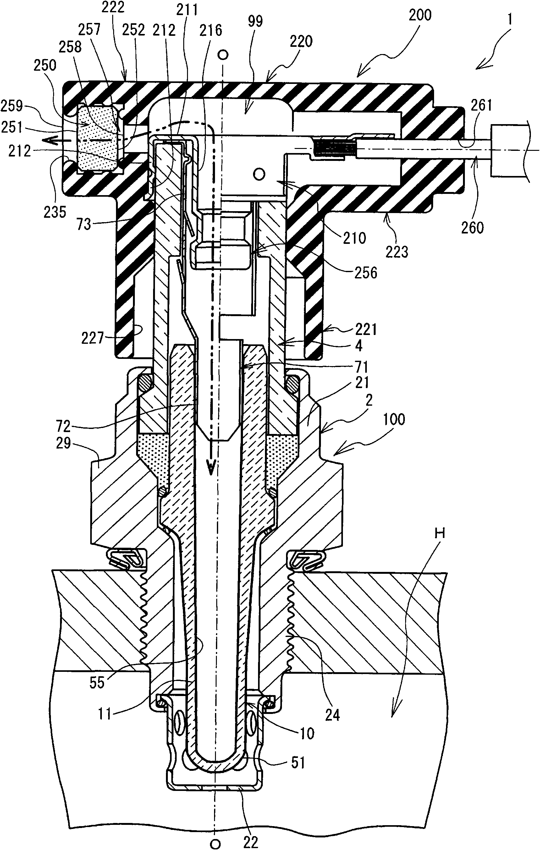
[0031] Next, a first embodiment of the gas sensor unit 1 that embodies the present invention will be described with reference to the drawings. The gas sensor unit 1 is installed and used in an exhaust path H of an automobile. In the following description, the side of the gas sensor unit 1 inserted into the exhaust path H in the axis O direction ( figure 1 The lower side in the middle) is regarded as the front end side of the gas sensor unit 1, and the side facing the opposite direction of this side ( figure 1 The upper side) is regarded as the rear end side.

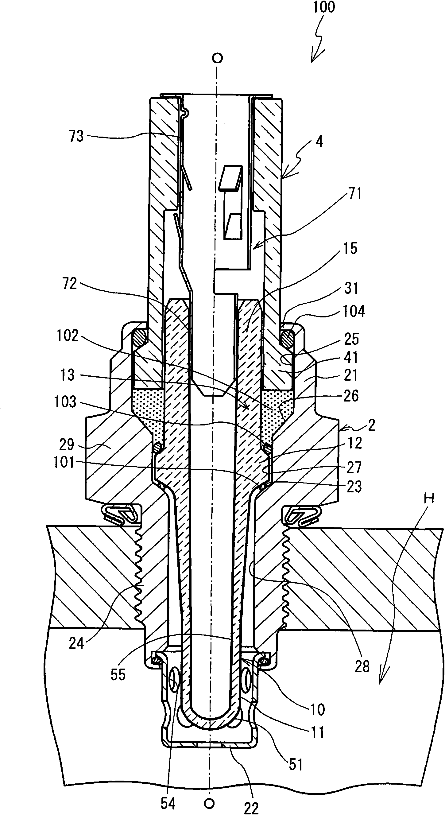
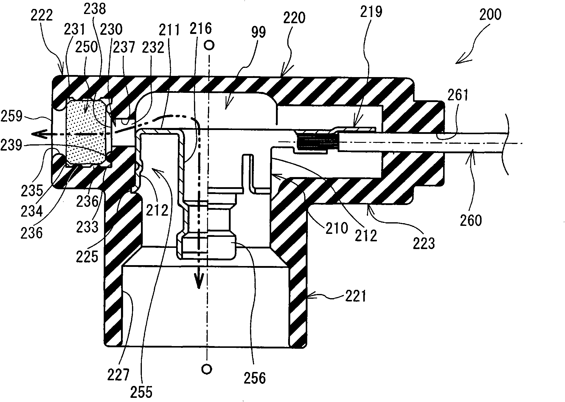
[0032] Such as figure 1 As shown, the gas sensor unit 1 includes an oxygen sensor 100 and a sensor cap 200 detachably attached to the oxygen sensor 100 at the rear end side of the oxygen sensor 100 . The oxygen sensor 100 has a built-in detection element 10 that is exposed to the exhaust gas for outputting a detection signal corresponding to the oxygen concentration in the exhaust gas. The sensor cap 200 is mounted o...


PUM


Abstract

The present invention provides gas sensor unit capable of ensuring the ventilation volume. A first protruding part (239) is arranged on the connection surface (233) in the filter configuration hole (231). The inner surface (252) of the filter member (250) configured in the filter configuration hole (231) is only contacted to the front end part of the protruding part (239). A gap (257) is formed between the inner surface (252) and the connection surface (233), so as to prevent the close contact of the inner surface (252) and the connection surface (233). At this point, parts on the inner surface (252) except the part contacted with the filter configuration hole (231) totally face to the gap (257). Therefore, compared with the prior instance that the inner surface (252) and the connection surface (233) are in close contact, the ventilating area in the inner surface (252) can be increased, thereby increasing the ventilation volume in the filter member (250).

Description

technical field [0001] The invention relates to a gas sensor unit having a detection element for detecting the oxygen concentration in exhaust gas. Background technique [0002] Conventionally, an oxygen sensor is known which incorporates a detection element for detecting the concentration of oxygen contained in exhaust gas of an automobile and is installed in an exhaust path of an internal combustion engine or the like. A detection electrode exposed to exhaust gas and a reference electrode exposed to air are provided in the detection element of the oxygen sensor. Furthermore, a sensor cap having a cap terminal connected to the reference electrode and used to obtain the output of the detection element is detachably attached to the oxygen sensor. A gas sensor unit is formed by an oxygen sensor and a sensor cap. [0003] The sensor cap also includes a surrounding member for holding the cap terminal and mounted on the oxygen sensor. And, in the state where the sensor cap is ...

Claims


Application Information

Patent Timeline
Patent Type & Authority Applications(China)
IPC IPC(8): G01N27/409
Inventor 松原仪明安田功二郎浅井昌弘
Owner NGK SPARK PLUG CO LTD
Learn More