Electric push device
A propulsion device, electric technology, applied in the direction of electromechanical devices, electric components, electrical components, etc., can solve the problems of unable to automatically restore the initial state, many failures, temperature rise and other problems, to achieve energy saving, wide range of uses, reduce temperature rise and other problems. Effect
- Summary
- Abstract
- Description
- Claims
- Application Information
AI Technical Summary
Problems solved by technology
Method used
Image
Examples
Embodiment 1
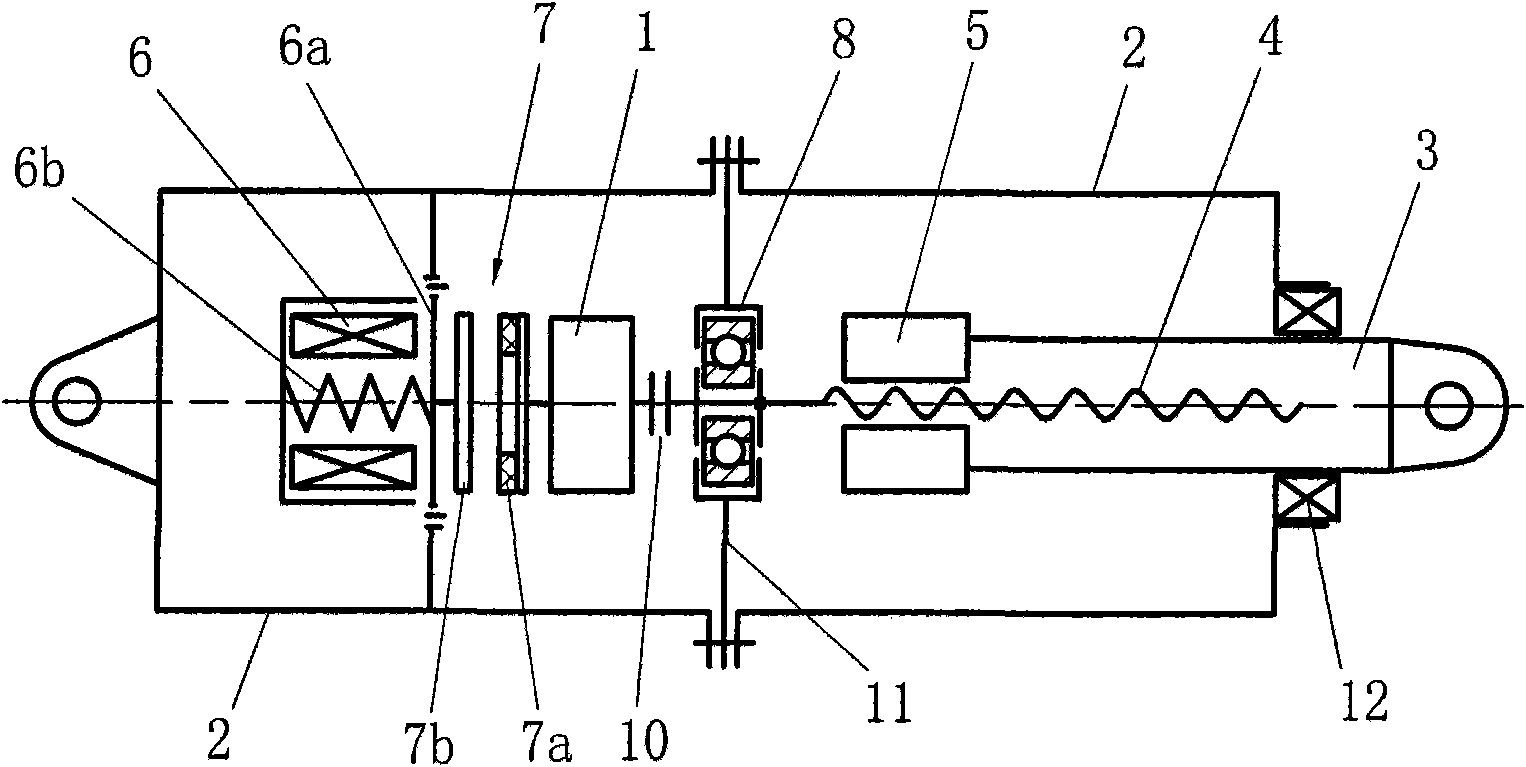
[0029] Example 1, see figure 1 .
[0030] The technical scheme of object of the present invention sees figure 1 , including a motor 1 and a casing 2, the casing 2 is provided with a push rod 3 that can move axially, the push rod 3 is provided with a screw 4, the push rod 3 is provided with a nut 5 that forms a threaded pair with the screw 4, and the screw The rod 4 and the nut 5 preferably adopt a ball screw and ball nut structure. The helix angle of the screw rod 4 and the nut 5 is greater than the self-locking angle. Connected to the housing 2, the inner end of the screw rod 4 is connected to the shaft of the motor 1. In this example, the motor 1 is located between the brake pair 7 and the inner end of the screw rod (4), and the inner end of the screw rod 4 is connected to the motor 1 The output shaft connection, such as figure 1 As shown, the inner end of the screw rod 4 is connected to the output shaft of the motor 1 through a coupling 10; an electromagnet 6 and a brake...
Embodiment 2
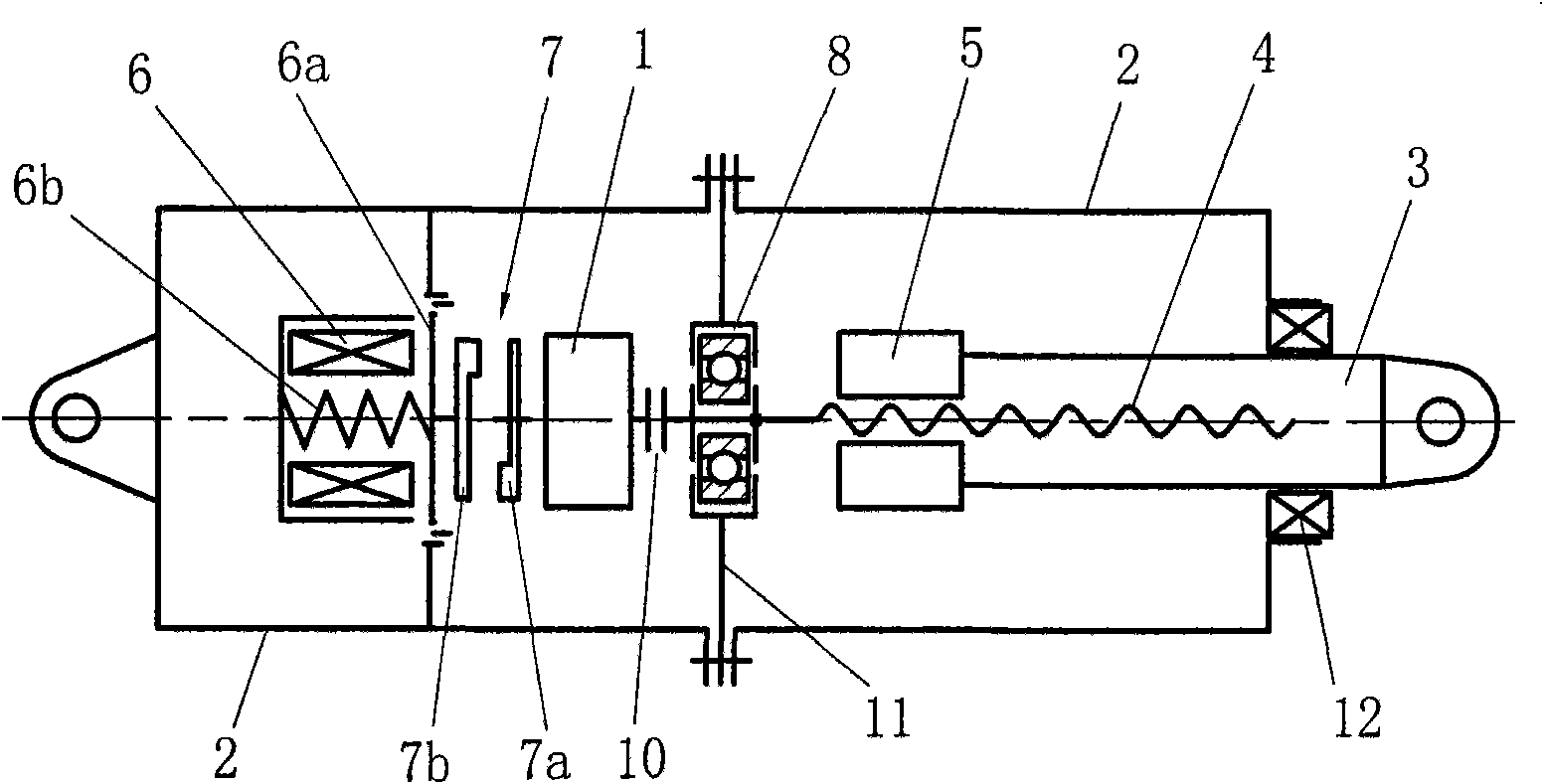
[0032] Example 2, see figure 2 .
[0033] This embodiment is based on Embodiment 1, and the structure of the brake pair 7 is deformed, figure 1 The rotary brake disc 7a and the dynamic brake disc 7b of the brake pair 7 shown in the figure are annular joint surfaces, and the rotary brake disc 7a and the dynamic brake disc 7b of the brake pair in this example are boss-type joint surfaces. Others are described in Example 1.
Embodiment 3
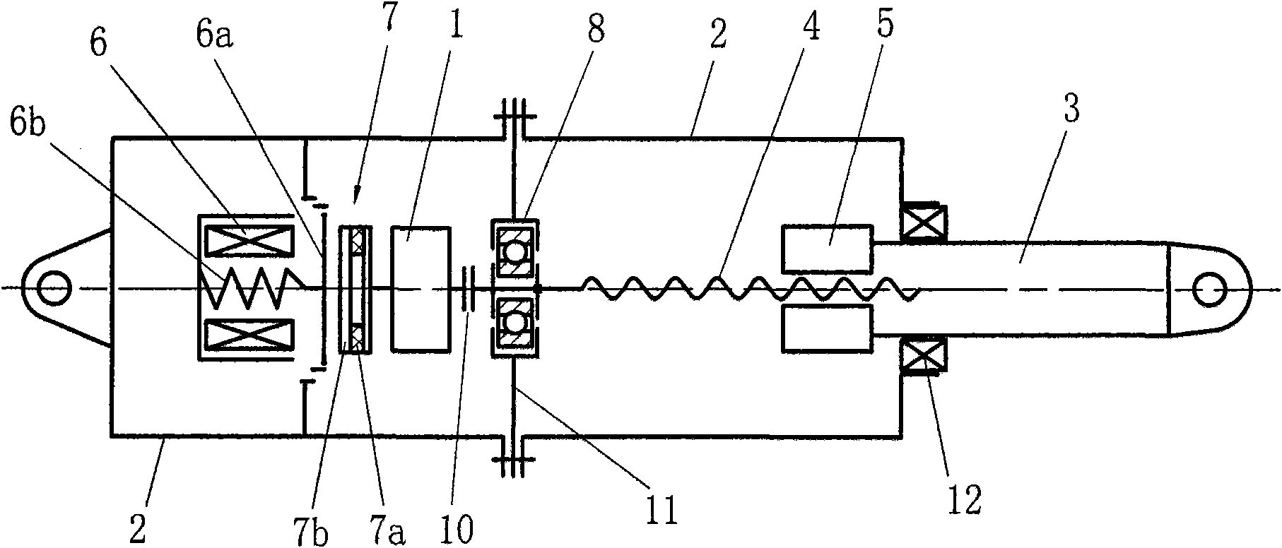
[0034] Example 3, see image 3 .
[0035] The difference between this example and Example 1 is that the initial position of the nut 5 on the push rod 3 is located at the outer end of the screw 4. When the motor 1 is energized and rotates, the push rod 3 shrinks inward along the screw 4 along with the nut 5. To move forward, the push rod 3 is equivalent to retracting inwardly, that is, to pull the components or mechanisms connected with the push rod; the electromagnet 6 is in a power-off state, such as figure 1 As shown, the dynamic brake disc 7b and the rotating brake disc 7a are in a combined state, that is, the braking force generated by the combination of the dynamic brake disc 7b and the rotating brake disc 7a keeps the push rod 3 outside the screw rod 4 The state after the end. Others are the same as embodiment 1.
PUM
 Abstract
Description
Claims
Application Information
 - R&D
- Intellectual Property
- Life Sciences
- Materials
- Tech Scout
- Unparalleled Data Quality
- Higher Quality Content
- 60% Fewer Hallucinations
Browse by: Latest US Patents, China's latest patents, Technical Efficacy Thesaurus, Application Domain, Technology Topic, Popular Technical Reports.
© 2025 PatSnap. All rights reserved.Legal|Privacy policy|Modern Slavery Act Transparency Statement|Sitemap|About US| Contact US: help@patsnap.com


