Glass substrate inspecting apparatus and glass substrate inspecting method

A technology for glass substrates and inspection devices, applied in measuring devices, material analysis through optical means, instruments, etc., can solve the problems of unsatisfactory, impractical, complex and large-scale devices, etc., and achieve the effect of correcting bending and improving detection accuracy

Active Publication Date: 2010-11-17
NIPPON ELECTRIC GLASS CO LTD
View PDF10 Cites 16 Cited by
  • Summary
  • Abstract
  • Description
  • Claims
  • Application Information

AI Technical Summary

Problems solved by technology

However, in the method disclosed in the above-mentioned Patent Document 2, the glass substrate is fixed at a fixed position, and only the lighting device and the camera are moved, so the above requirements cannot be met.
Furthermore, if the glass substrate is moved in the width direction while holding all four sides of the glass substrate in order to meet the requirements, since the clamping mechanism is also located in the moving direction, the device for moving the glass substrate is complicated and enlarged. Not practical

Method used


Image

  • Glass substrate inspecting apparatus and glass substrate inspecting method
  • Glass substrate inspecting apparatus and glass substrate inspecting method

Examples


Embodiment Construction

[0039] Hereinafter, an embodiment of the present invention will be described with reference to the drawings.

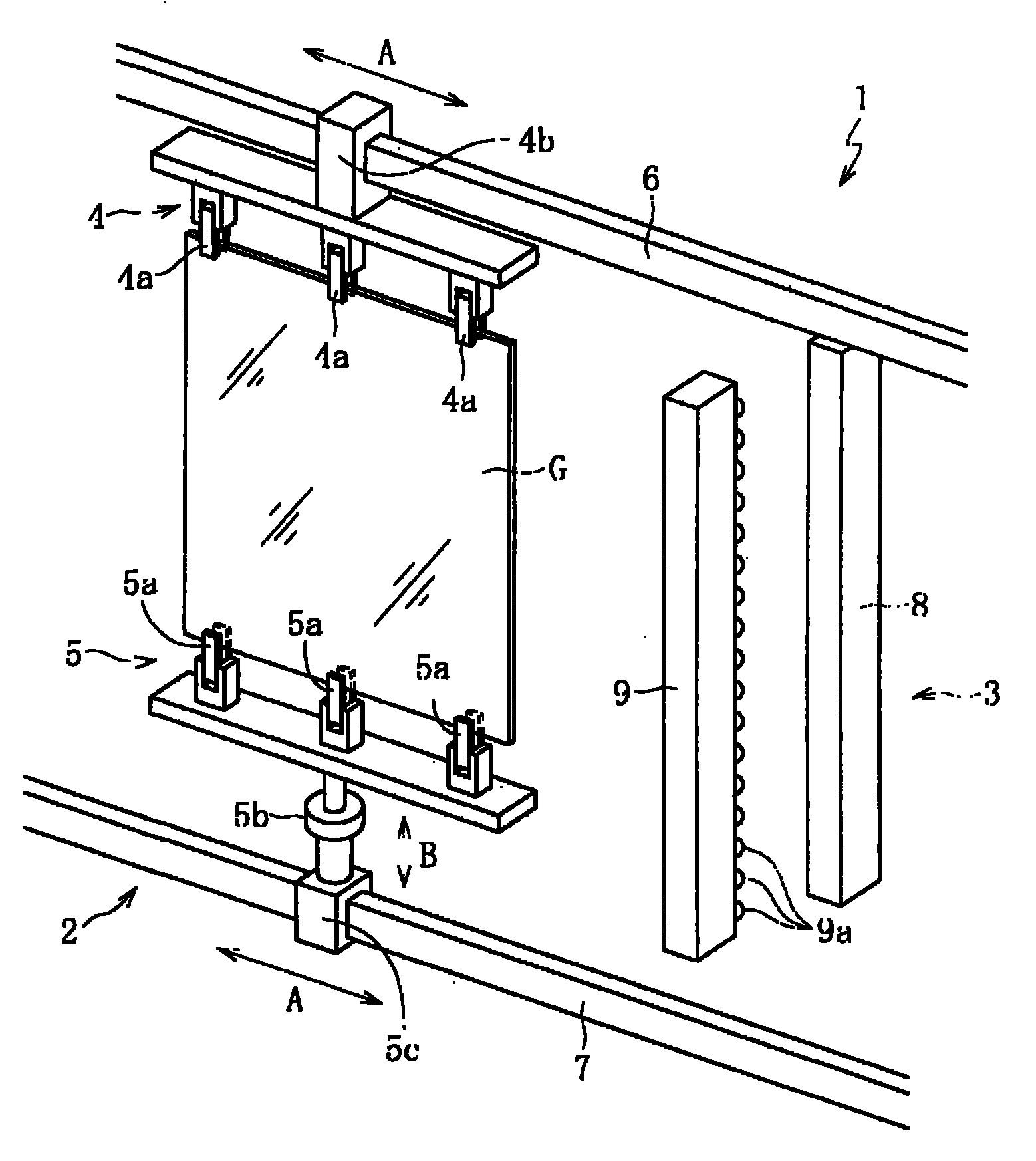
[0040] figure 1 It is a side view showing the overall structure of the glass substrate inspection apparatus of this embodiment. As shown in the figure, this glass substrate inspection apparatus 1 includes: a moving mechanism 2 that moves the glass substrate G in a vertical posture (approximately vertical posture in the illustration); The defect detection mechanism 3 that detects defects of the glass substrate G on the moving path. Moreover, as glass substrate G, the glass substrate for liquid crystal displays whose thickness is 0.05-1.8 mm and the size of one side is 1 m or more is mentioned, for example.

[0041] The above-mentioned moving mechanism 2 is provided with: an upper holding mechanism 4 for holding the top of the glass substrate G; a lower holding mechanism 5 for holding the lower edge of the glass substrate G; An upper guide rail 6 for guiding; a lower...


PUM


Abstract

Defect inspection accuracy is improved by correcting warping of a glass substrate without generating excessive stress concentration on a side of the glass substrate, while meeting a demand of inspecting defects with a simple apparatus constitution while the glass substrate is being shifted. A glass substrate inspecting apparatus (1) inspects existence of defects included in a glass substrate (G) by scanning the glass substrate (G) by using a defect detecting means (3) by relatively moving the glass substrate (G) in the vertical posture to the defect detecting means (3) in the width direction of the glass substrate (G). The glass substrate inspecting apparatus is provided with an upper holding means (4) which holds the upper side of the glass substrate (G), and a lower holding means (5) which holds the lower side of the glass substrate (G). The glass substrate (G) is held only by the upper holding means (4) and the lower holding means (5), and the upper holding means (4) and the lower holding means (5) are separated one from the other. The glass substrate (G) is shifted in the width direction toward the defect detecting means (3), in a state where tension is applied to the glass substrate (G) in the vertical direction.

Description

technical field [0001] The present invention relates to a glass substrate inspection device and a glass substrate inspection method for inspecting whether a glass substrate contains defects. Background technique [0002] As is well known, a molten glass melted in a melting furnace is formed into a ribbon-shaped glass ribbon, and after the glass ribbon is sufficiently cooled, it is cut into a predetermined size to produce a liquid crystal display, a plasma display, an electroluminescence display, Various glass plates including glass substrates for flat panel displays (FPDs) such as field emission displays. Here, in shaping|molding of a glass ribbon, the down-draw method, such as an overflow down-draw method (melt method) or a slot down-draw method, etc. are normally utilized other than a float method. [0003] Then, the glass substrates (small glass substrates including chamfered sample glass substrates) produced through this process are usually sent to the inspection proces...

Claims


Application Information

Patent Timeline
Patent Type & Authority Applications(China)
IPC IPC(8): G01N21/958G01N21/84
CPCG01N21/958
Inventor 外间喜春山本正善安井忠德
Owner NIPPON ELECTRIC GLASS CO LTD
Why Eureka
Try Eureka