Elliptic motion machine

The technology of an elliptical exercise machine and a crossbar is applied in sports accessories, training equipment for adjusting the cardiovascular system, training equipment for adjusting coordination, etc. It can solve the problems of high production cost, high power output, large motor output, and low work efficiency. , to achieve the effect of good appearance, stable support structure and high working efficiency

Active Publication Date: 2010-11-24
乔山健身器材(上海)有限公司
View PDF5 Cites 4 Cited by
  • Summary
  • Abstract
  • Description
  • Claims
  • Application Information

AI Technical Summary

Problems solved by technology

From a mechanical point of view, this frame body 95 can be regarded as a "first type of lever", wherein, since the length between the point of application of the driving device 96 and the pivot point 97 of the frame body (ie, the force arm) is smaller than that of the cantilever arm 94 The length (i.e., the resistance arm) between the suspension point and the pivot point 97 of the frame makes the working efficiency of the driving device 96 relatively low, so a motor with a large output force is required, resulting in relatively low production cost and consumed electric power. high
It should be noted that, under such circumstances, directly moving the pivot point 97 on the elevated frame body 95 to change the ratio of the force application arm to the force resistance arm is not an ideal method to solve the above-mentioned problem, because this method will Shortening the deflection range at the top of the cantilever 94, increasing the space requirement of the driving device, and reducing the response efficiency when adjusting the trajectory, in short, the disadvantages outweigh the advantages
[0007] (2) In addition, under the above-mentioned structure, the driving device 96 is generally arranged in the center between the left and right (enabling symmetrical force on the aforementioned U-shaped frame), therefore, when the relative relationship of the components is set at the design stage , in order not to interfere with the driving device 96 at the bottom (and the protective case cover not shown in the figure), and to keep a safe distance from accidents of pinching, the height of the lowest point of the support rod 92 must be moderately increased, causing the pedal 91 is supported to move to a higher position, thus affecting the user's convenience when boarding the pedal 91 and the sense of security when exercising
[0012] In the various known elliptical exercise machines with adjustable pedal tracks, the driving device is not well integrated with the existing structure. In addition to the need to design an additional cover to cover and cover, resulting in increased cost, increased volume, and complicated appearance, What's more serious is that as mentioned earlier, in design, because other components have to dodge or pull the driving device, the degree of freedom of design and ergonomic characteristics are reduced
[0013] Furthermore, in the various known elliptical exercise machines that can adjust the pedal trajectory, the user can only know the current slope of the pedal trajectory through the electronic data displayed on the console, and cannot intuitively observe the spatial relationship of the main components of the exercise machine. visual judgment
What's more, most of the adjustment components (such as cantilever and support body) in most known structures are not located in front of the user's eyes, so that the adjustment of the slope of the pedal track is not intuitive enough, but must be obtained through data.

Method used


Image

  • Elliptic motion machine
  • Elliptic motion machine
  • Elliptic motion machine

Examples


Embodiment Construction

[0037] In order to describe the structure, features and achieved effects of the present invention in detail, a preferred embodiment is given and described as follows with accompanying drawings.

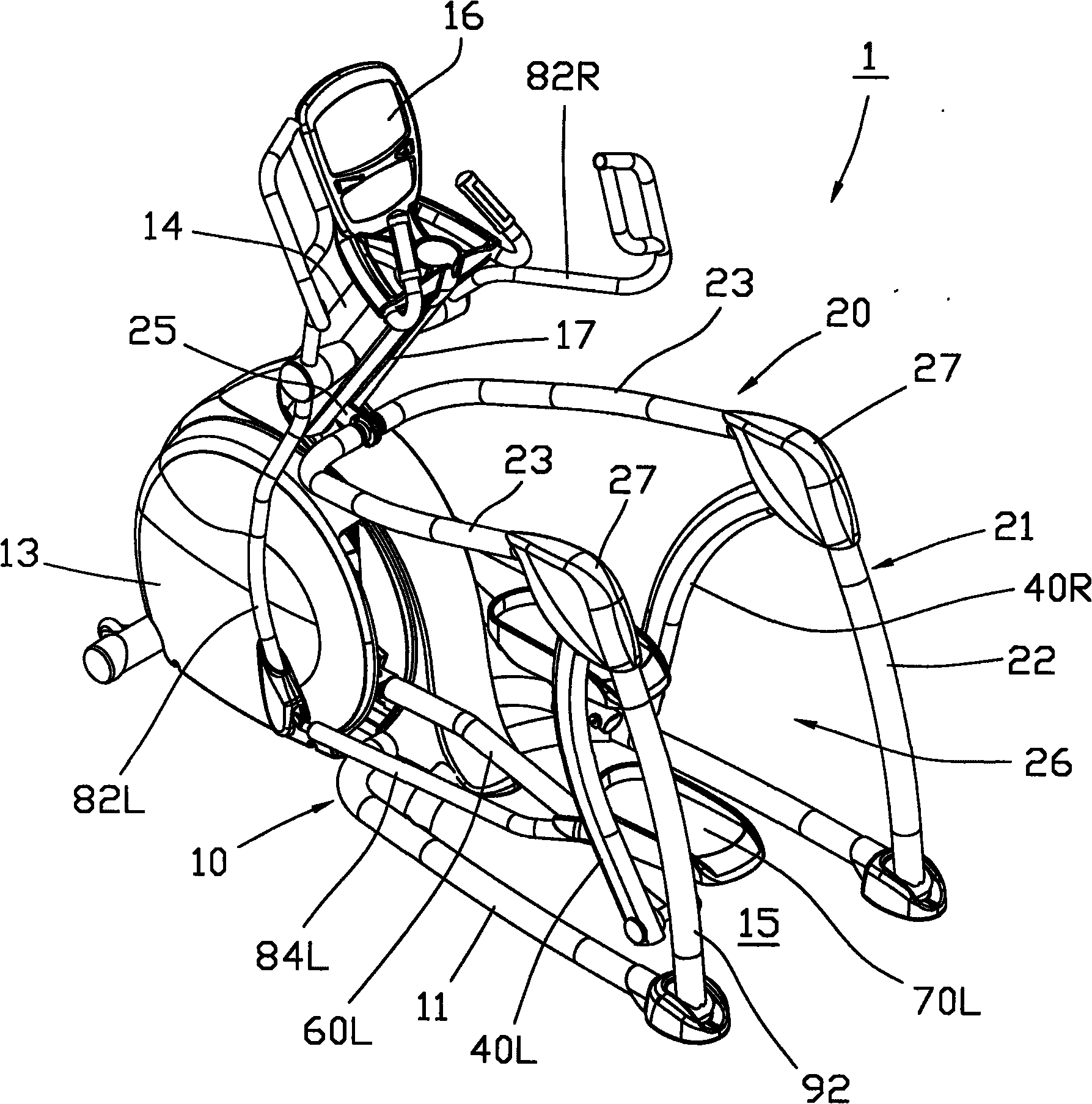
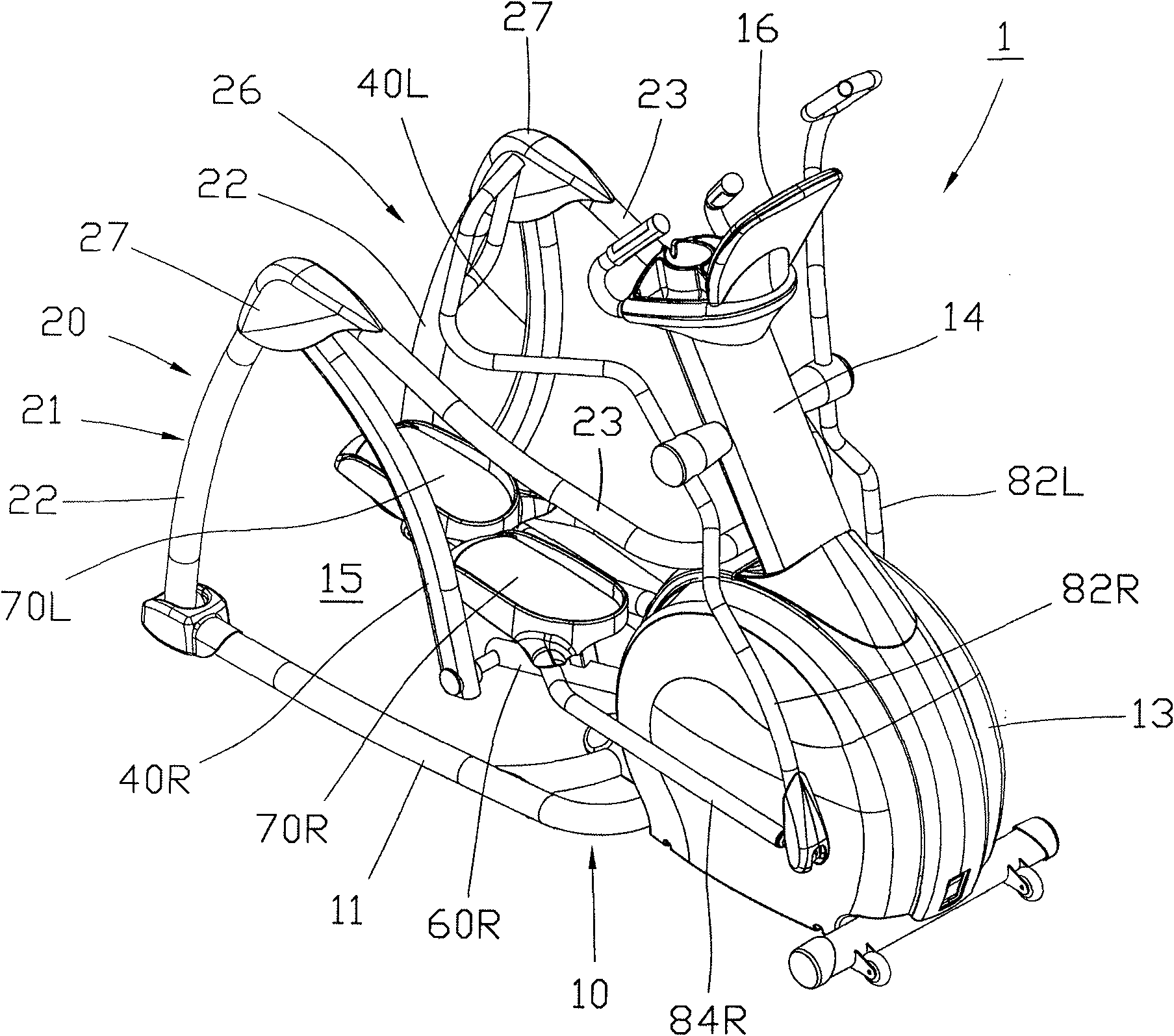
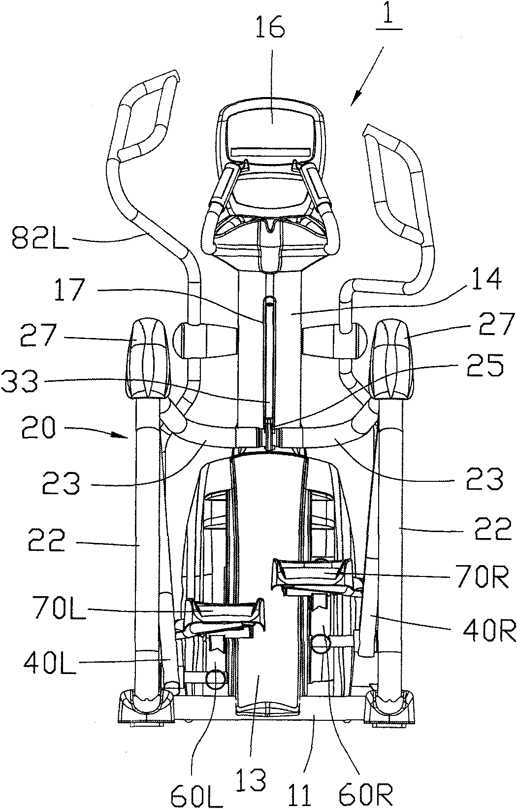
[0038] Such as Figure 1 to Figure 6 As shown, the elliptical exercise machine 1 has a skeleton 10 used as the basis for installing other components, which mainly includes a base 11 placed flat on the ground, a base 12 fixed on the top side of the front end of the base 11 (such as Figure 5 As shown, it is covered by a shell cover 13), and a hollow instrument rod 14 extending upwards from the top of the support 12. The rear half of the base 11 forms a U-shaped hollow area 15 that is open up and down and has an open rear end. A console 16 is provided on the top of the instrument pole 14 .

[0039] In addition, a movable frame 20 is provided on the rear half of the frame 10, and the movable frame 20 is formed by combining two symmetrical left and right frame bodies 21. Each frame body...


PUM


Abstract

The invention relates to an elliptic motion machine, comprising a skeleton and left and right skeleton bodies, left and right cantilevers, left and right support bars and left and right footboards, wherein each skeleton body comprises a longitudinal rod section and a transverse rod section; the two longitudinal rod sections are respectively erected at left and right sides of the rear end of the skeleton, and the bottom end of each longitudinal rod section is connected at the bottom part of the skeleton; the two transverse rod sections extend at the left and sides along the fore-aft direction, the rear end of each transverse rod section is connected on the top end of the corresponding longitudinal rod section, and the front end of each transverse rod section is connected at the front end of the skeleton; an in-out space, the front and back parts of which are unblocked, is formed between the two longitudinal rod sections; the left and right cantilevers respectively provided with a hanging end and a swing end, and the hanging ends of the left and right cantilevers are respectively pivoted on the left and right skeleton bodies; the left and right support bars are respectively provided with a rewind part and a swing part positioned at the rear part of the rewind part, the rewind parts move on a closed track relative to the skeleton, and the swing parts are pivoted at the swing ends of the corresponding cantilevers; and the left and right footboards are directly or indirectly supported by the two support bards respectively. A user of the invention can intuitively know the inclined degree of the tracks of the footboards.

Description

[0001] This case is a divisional application, the original patent application number is 200710106184.X, the application date is June 22, 2007, and the name is "elliptical exercise machine with adjustable pedal trajectory". technical field [0002] The present invention relates to exercise and fitness equipment, in particular to an elliptical exercise machine (Elliptical). Background technique [0003] The elliptical exercise machine is a kind of sports and fitness equipment that can carry the user's feet with the left and right pedals, and then guide the feet to move on an elliptical trajectory. In the prior art, the pedal trajectory of some elliptical exercise machines can be adjusted by the user according to individual needs, so as to change the stride range, exercise difficulty or exercise parts. [0004] Such as Figure 12 Shown is a kind of known elliptical exercise machine 9 that can adjust pedal track (note: details can refer to Chinese No. 1958099 early publication p...

Claims


Application Information

Patent Timeline
IPC IPC(8): A63B22/04
Inventor 马克·康乃尔
Owner 乔山健身器材(上海)有限公司
Why Eureka
Try Eureka