Supercharge Your Innovation With Domain-Expert AI Agents!

Heat exchanger holding device

A technology for clamping devices and heat exchangers, applied in auxiliary devices, auxiliary welding equipment, welding/cutting auxiliary equipment, etc., can solve problems such as deformation of heat exchangers, difficulty in installation, and influence on processing and installation of heat exchangers. Achieve the effects of preventing deformation and damage, saving binding materials, and improving the qualified rate

Inactive Publication Date: 2014-06-18
SANHUA(HANGZHOU) MICRO CHANNEL HEAT EXCHANGER CO LTD +1
View PDF3 Cites 0 Cited by
  • Summary
  • Abstract
  • Description
  • Claims
  • Application Information

AI Technical Summary

Problems solved by technology

[0003] However, due to factors such as structural design and thermal expansion and contraction of materials during the welding process, the heat exchanger is deformed. Since the heat exchanger needs to be installed in the box together with other accessories, the volume of the box is fixed and limited. The installation accuracy of the heat exchanger is very high, so the deformation of the heat exchanger will seriously affect the subsequent processing and installation of the heat exchanger, making the installation size out of tolerance, resulting in difficulty in installation
At the same time, in the process of processing, after the heat exchanger is assembled and before entering the brazing furnace for welding, the heat exchange tubes and fins are fixed with strapping straps and binding rods. The device is easily deformed
After the welding is completed, the strapping cannot be reused, resulting in waste of materials
Moreover, during the handling process before welding, the heat exchanger is easily deformed and damaged

Method used


Image

  • Heat exchanger holding device
  • Heat exchanger holding device
  • Heat exchanger holding device

Examples


Embodiment Construction

[0022] Embodiments of the present invention are described in detail below, examples of which are shown in the drawings, wherein the same or similar reference numerals designate the same or similar elements or elements having the same or similar functions throughout. The embodiments described below by referring to the figures are exemplary only for explaining the present invention and should not be construed as limiting the present invention.

[0023] In the description of the present invention, the orientation or positional relationship indicated by the terms "longitudinal", "transverse", "upper", "lower", "left", "right" etc. is based on the orientation or positional relationship shown in the drawings, The disclosure is merely for convenience in describing the invention and does not require that the invention must be constructed and operated in a particular orientation, and thus should not be construed as limiting the invention.

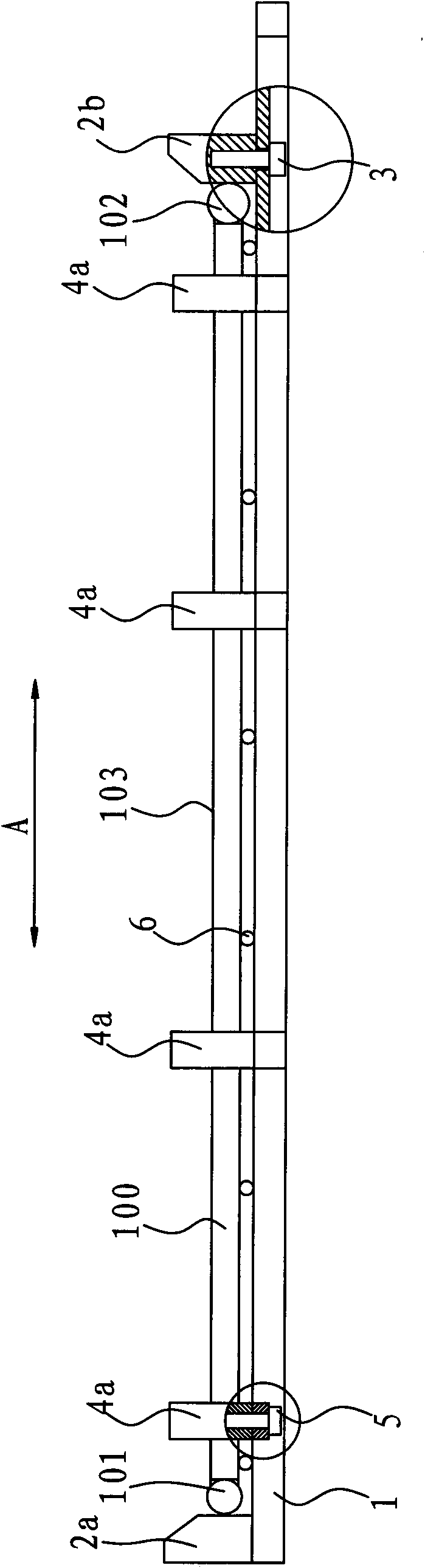
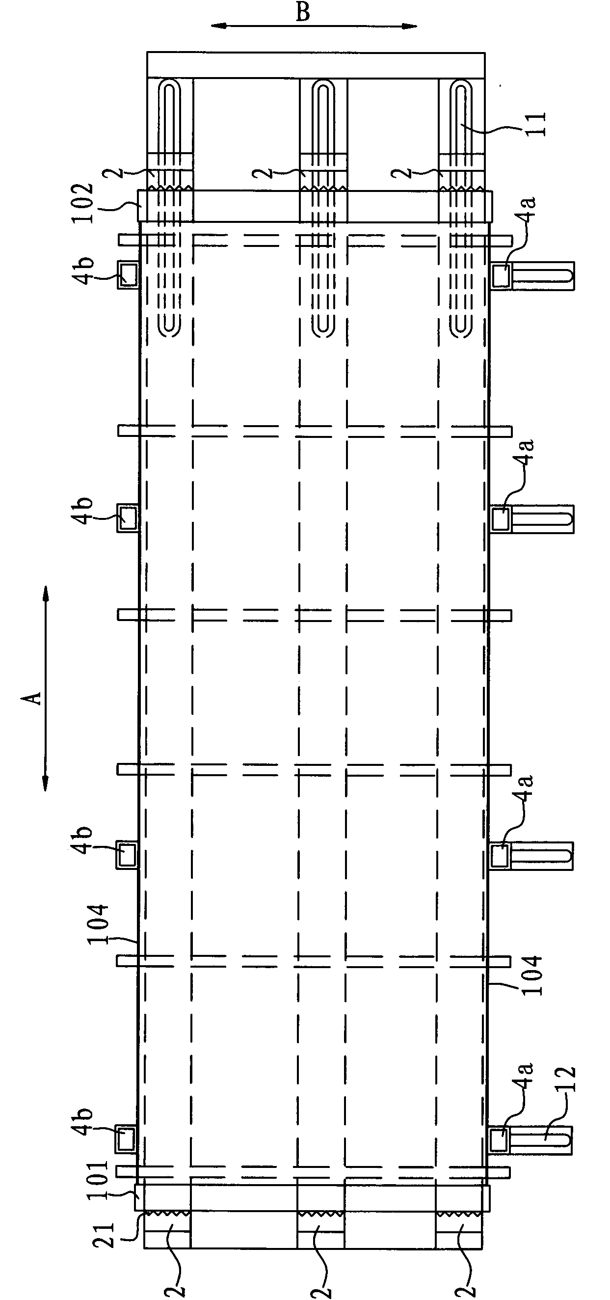
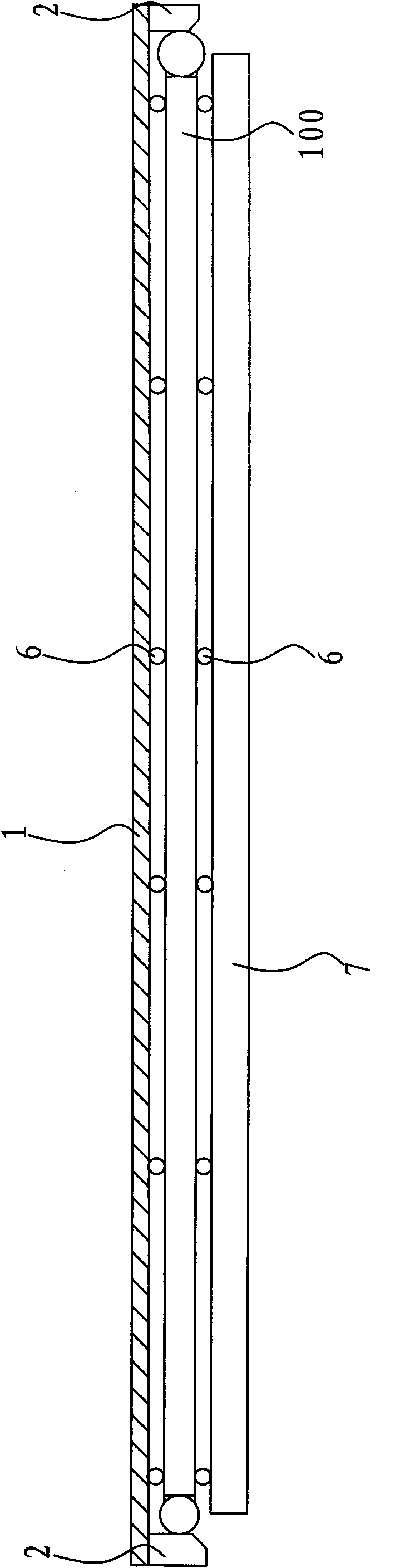
[0024] A heat exchanger clamping device accor...


PUM


Abstract

The embodiment of the invention provides a heat exchanger holding device, comprising a bracket, a first vertical holding block, a second vertical holding block, first transverse holding blocks and second transverse holding blocks, wherein the first vertical holding block and the second vertical holding block are respectively arranged at the two vertical ends of the bracket; at least one of the first vertical holding block and the second vertical holding block can move vertically; the first transverse holding blocks and the second transverse holding blocks are respectively arranged at the two transverse sides of the bracket; and at least the first transverse holding blocks or the second transverse holding blocks can move transversely. The device can reduce deformation of the heat exchanger in the process of welding, effectively protect the heat exchanger from deformation and damage in the process of transport, improve the manufacturing precision of the heat exchanger, reduce the use of strapping materials and lower the manufacturing cost of the heat exchanger.

Description

technical field [0001] The invention relates to the technical field of heat exchanger manufacturing, in particular to a heat exchanger clamping device. Background technique [0002] A typical traditional heat exchanger includes a pair of headers parallel to each other and spaced apart from each other, heat exchange tubes at both ends respectively communicated with the inner chambers of the two headers, and heat exchange tubes arranged between adjacent heat exchange tubes Fins, and two side plates fixedly connected to the two outermost heat exchange tubes through the fins. In the manufacturing process, first insert the two ends of the heat exchange tubes into the holes of the header respectively, then place the fins between the adjacent heat exchange tubes, then place the binding rods on the outside of the two side plates, and use the binding tape (steel wire or steel belt) to bind and fix the heat exchanger along the height direction, and finally prevent the heat exchanger ...

Claims


Application Information

Patent Timeline
Patent Type & Authority Patents(China)
IPC IPC(8): B23K3/08B23K37/04
Inventor 陈红兵
Owner SANHUA(HANGZHOU) MICRO CHANNEL HEAT EXCHANGER CO LTD
Features
  • R&D
  • Intellectual Property
  • Life Sciences
  • Materials
  • Tech Scout
  • Unparalleled Data Quality
  • Higher Quality Content
  • 60% Fewer Hallucinations
Learn More