Pneumatic tire

A pneumatic tire, tire technology, applied in tire parts, tire tread/tread pattern, transportation and packaging, etc., to achieve the effect of balancing driving stability on dry roads, ensuring drainage, and balancing driving stability on wet roads

Active Publication Date: 2010-11-24
THE YOKOHAMA RUBBER CO LTD
View PDF4 Cites 32 Cited by
  • Summary
  • Abstract
  • Description
  • Claims
  • Application Information

AI Technical Summary

Problems solved by technology

Contents of the invention

Method used


Image

  • Pneumatic tire
  • Pneumatic tire
  • Pneumatic tire

Examples


Embodiment

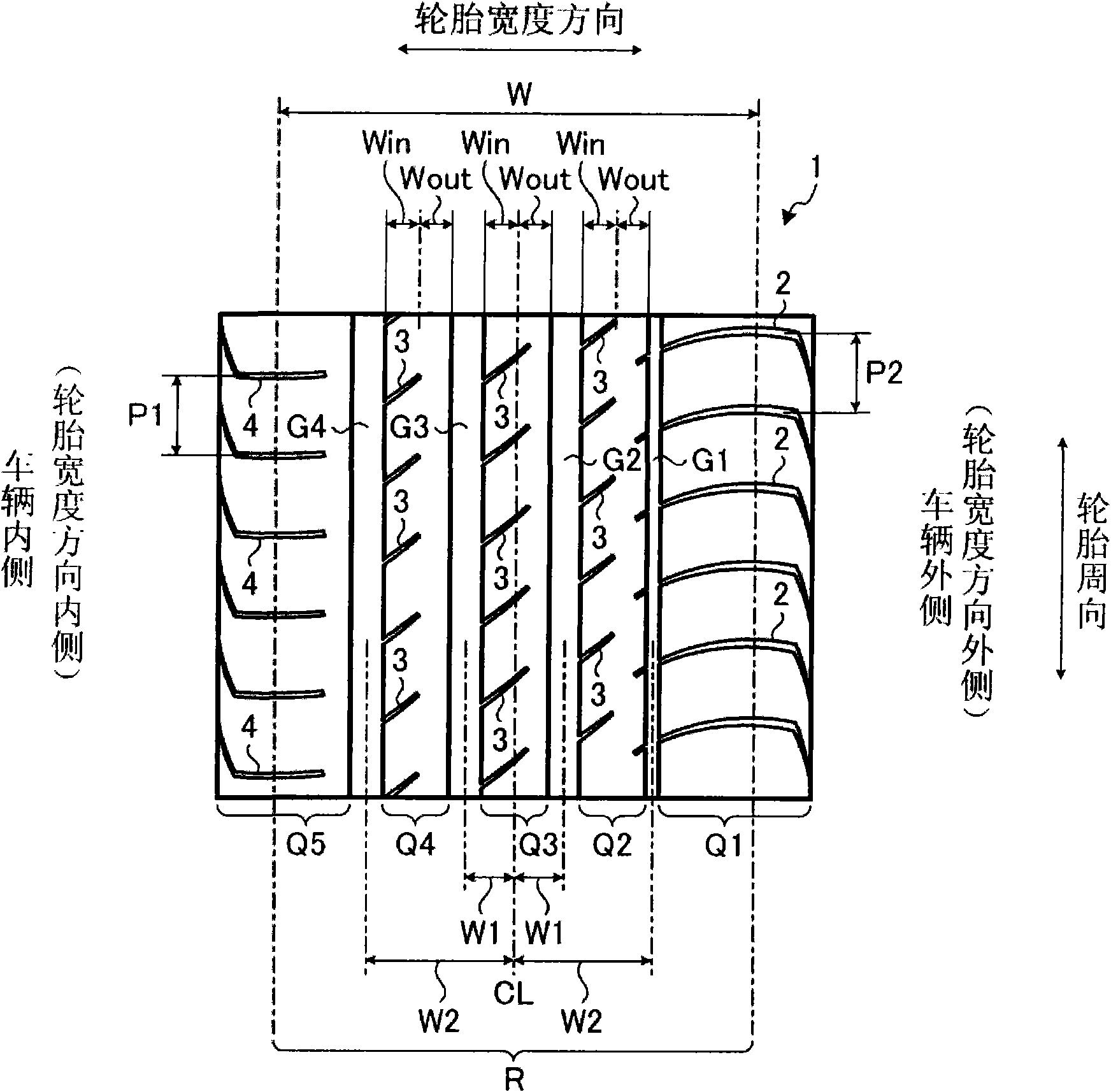
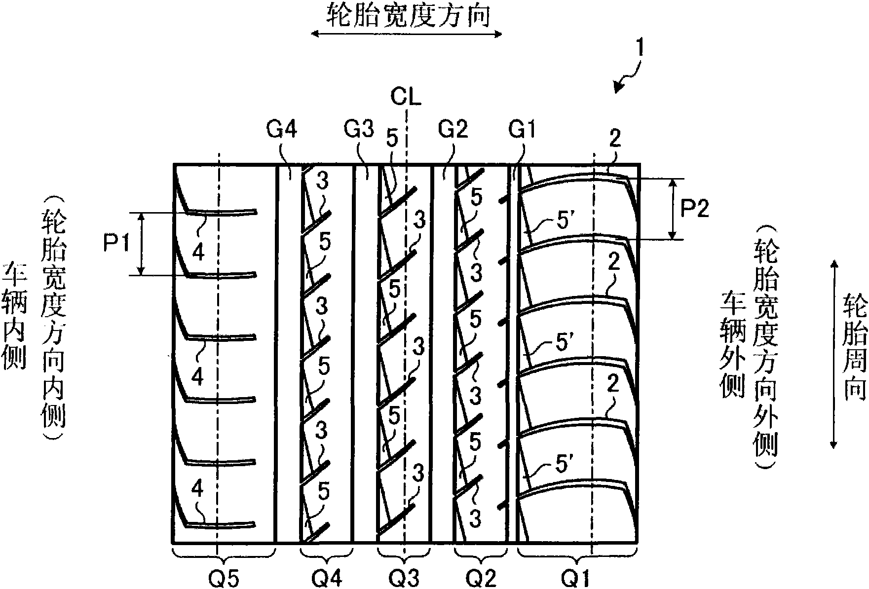
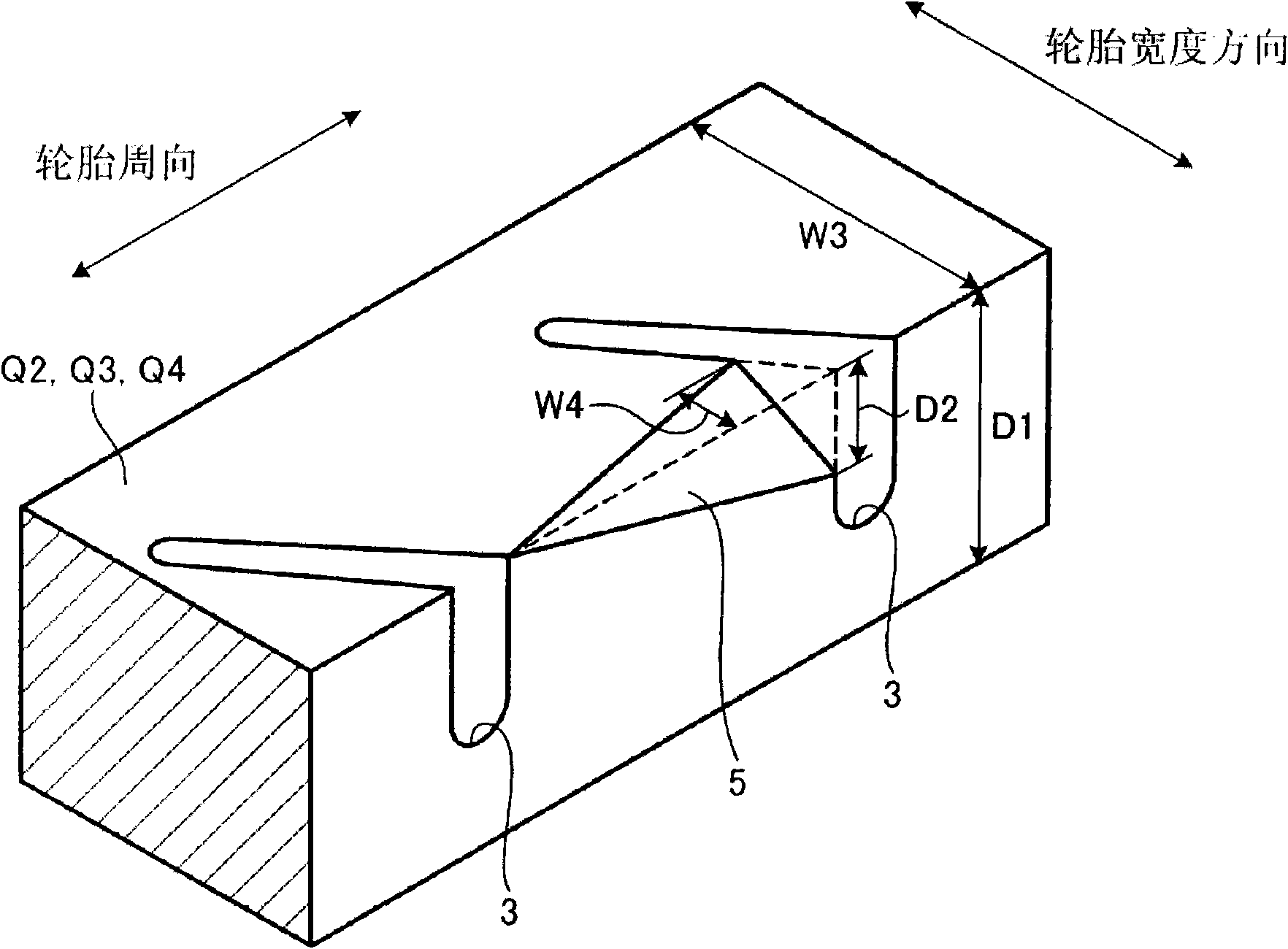
[0067] Take 245 / 40R18 as the tire size, and figure 1 For the basic shape of the tread pattern, tires of the present invention (Examples 1-8) were made respectively, which had figure 1 and figure 2 Shown pattern structure; Comparative tire (comparative example 1), the pattern structure that it has is main groove G1, G2, G3, the groove width of G4 is identical, and as Figure 4 As shown, the inclined groove 3 is connected with the main groove G1, G2, G3 and the horizontal groove 2, 4 is not configured; the comparison tire (comparative example 2) has a pattern structure such as Figure 5 shown in Figure 4 The two shoulders of the tire are configured with rib grooves 2 and 4 connected to the main grooves G1 and G4; the comparative tire (Comparative Example 3) has a pattern structure such as Figure 6 As shown, will figure 1 The lug groove 4 is connected to the main groove G4; and the comparison tire (comparative example 4), such as Figure 7 As shown, its pattern structure ...


PUM


Abstract

A pneumatic tire including five land portions Q1, Q2, Q3, Q4, Q5 in a tread surface 1 by providing four main grooves G1, G2, G3, and G4 in a ground contact region R of the tread surface 1, wherein positions and groove widths of the main grooves G1, G2, G3, and G4 are specified together with only the land portion Q1 positioned outermost on a vehicle outer side when mounted on a vehicle being formed into a block row, and the other land portions Q2, Q3, Q4, and Q5 being formed into ribs, and a groove area proportion of the tread surface 1 is larger on a vehicle inner side than the vehicle outer side with a tire equator CL and center lines of the land portions Q2, Q3, Q4 as boundaries.

Description

technical field [0001] The invention relates to a pneumatic tire, in particular to a pneumatic tire capable of multi-dimensional driving stability on a dry road and driving stability on a wet road. Background technique [0002] In recent years, as the performance of vehicles continues to improve, there is an increasingly strong demand for pneumatic tires that can combine high-speed driving stability on dry roads and wet road driving stability in multiple dimensions. [0003] Generally speaking, a plurality of horizontal grooves or grooves have been arranged on the tire tread to ensure water drainage as a method of improving driving stability on wet roads. However, if this method is adopted, the rigidity of the land portion formed by the tread is lowered, and there is a problem that it is difficult to ensure driving stability on a dry road surface. [0004] In order to combine the contradictory driving stability on dry roads and driving stability on wet roads in multiple dim...

Claims


Application Information

Patent Timeline
Patent Type & Authority Applications(China)
IPC IPC(8): B60C11/12
CPCB60C2011/0381B60C11/0306B60C11/033B60C11/0304
Inventor 三田雅也
Owner THE YOKOHAMA RUBBER CO LTD
Why Eureka
Try Eureka