Method for tracing target object in panoramic video automatically

A target object, panoramic video technology, applied in the field of panoramic video technology and target tracking, can solve the problem of inappropriate detection and tracking of moving targets, and achieve the effect of reducing the search range, reducing search time, and ensuring speed and stability

Inactive Publication Date: 2010-11-24
BEIHANG UNIV +1
View PDF6 Cites 15 Cited by
  • Summary
  • Abstract
  • Description
  • Claims
  • Application Information

AI Technical Summary

Problems solved by technology

The position of the camera in this method is static, and the acquired video has a static background, so it is easy to track foreground objects using the method of background difference, which

Method used


Image

  • Method for tracing target object in panoramic video automatically
  • Method for tracing target object in panoramic video automatically
  • Method for tracing target object in panoramic video automatically

Examples


Example Embodiment

[0020] Specific implementation method

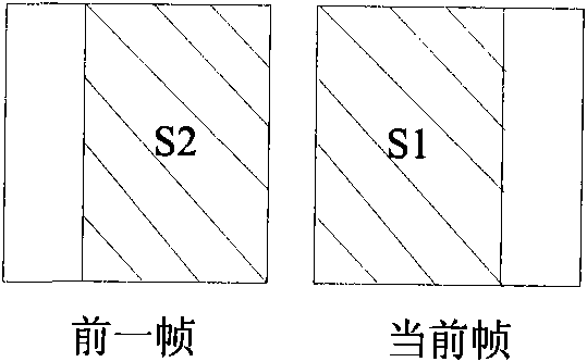
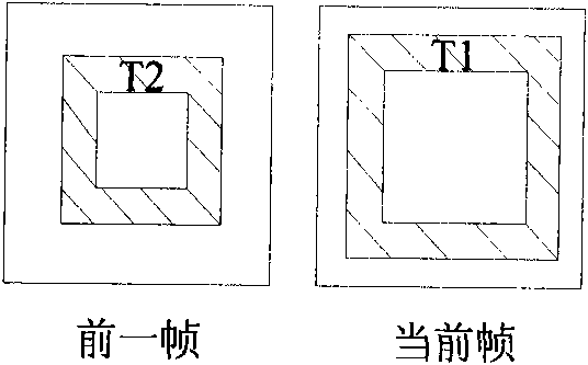
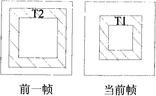
[0021] For continuous multi-frame panoramic images, the captured still scene will move in a specific direction and will move from one surface of the cube to the adjacent surface. Therefore, when tracking the target object, consider that the target is in the cube The movement on the adjacent surface is tracked by the movement trend of the pixel, as shown in Figure 1. Figure 1(a) shows the pixel correspondence between the current frame and the previous frame on the side of the cube. The S1 part of the current frame is the same as the S2 part of the previous frame. The two parts of the pixel only have a horizontal direction in position. Relative movement on the Figure 1(b) and Figure 1(c) respectively show the pixel correspondence between the current frame and the previous frame on the front and back of the cube. The T1 part of the current frame is similar to the T2 part of the previous frame. The process of the automatic tracking method for...


PUM


Abstract

The invention discloses a method for tracing a target object in a panoramic video automatically, which comprises the following steps: (1) acquiring the position of a target object in the panoramic video; (2) detecting if plane crossing appears in the motion of the target object in the cubic panorama, and performing a step (3) if plane crossing appears in the motion of the target object in the cubic panorama or performing a step (4) if plane crossing does not appear in the motion of the target object in the cubic panorama; (3) expanding an image on the original plane of the target object; (4) searching and matching along an epipolar line to obtain the motion vector of the target object; and (5) making a judgment according to the result of the step (4), if a matched target is found, ending the tracing or performing the step (2). The method can be used for tracing the target object in the panoramic video automatically and can narrow search range in a tracing process and ensure the quickness and stability of the tracing of the target object.

Description

technical field [0001] The present invention relates to the fields of panoramic video technology and object tracking, and more specifically, relates to a method for tracking objects in panoramic video. Background technique [0002] Panoramic images are stitched together from multiple real-world images taken at a certain point in different directions. Its specific generation process is: mapping overlapping images onto simple geometric surfaces, such as spheres, cubes or cylinders, and then stitching the projected images seamlessly to obtain panoramic images. According to the mapped geometry, panoramic images can be divided into cylindrical panoramic images, spherical panoramic images and cubic panoramic images. Panoramic video is composed of some time-related panoramic image sequences, from which a real panoramic scene can be obtained, and video frames can be positioned through time. [0003] The global motion of the cube panorama video of a still scene is usually dominated...

Claims


Application Information

Patent Timeline
IPC IPC(8): G06T7/20
Inventor 周忠牛犇陈珂吴威杨抒张军
Owner BEIHANG UNIV
Why Eureka
Try Eureka