
Microphone calibration method

A calibration method and microphone technology, applied to electrical components and other directions, can solve problems such as time-consuming and the inability of calibration devices to provide microphone phase calibration.

Inactive Publication Date: 2013-07-03
BEIHANG UNIV
View PDF3 Cites 0 Cited by
  • Summary
  • Abstract
  • Description
  • Claims
  • Application Information

AI Technical Summary

Problems solved by technology

The traditional calibration method is to use a single-frequency sound source such as B&K4228 or B&K4230 for single-frequency amplitude calibration, which requires the frequency response of the microphone to have a very good linearity. Only in this way can the sensitivity of a single frequency be used as the sensitivity of the entire frequency range. Sensitivity is used. If you want to use some microphones whose frequency response curve is not flat enough, it is impossible to use this sound source for calibration. In addition, when using a large number of microphones, the traditional calibration device can only be calibrated one by one, which is very time-consuming; In addition, many measurement applications require that the phase of the microphones used can be well matched, and the current calibration equipment cannot provide the phase calibration of the microphones

Method used


Image

  • Microphone calibration method
  • Microphone calibration method
  • Microphone calibration method

Examples


Embodiment Construction

[0066] The present invention will be further described below in conjunction with the accompanying drawings.

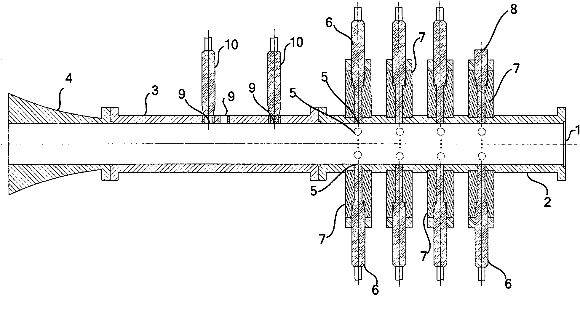
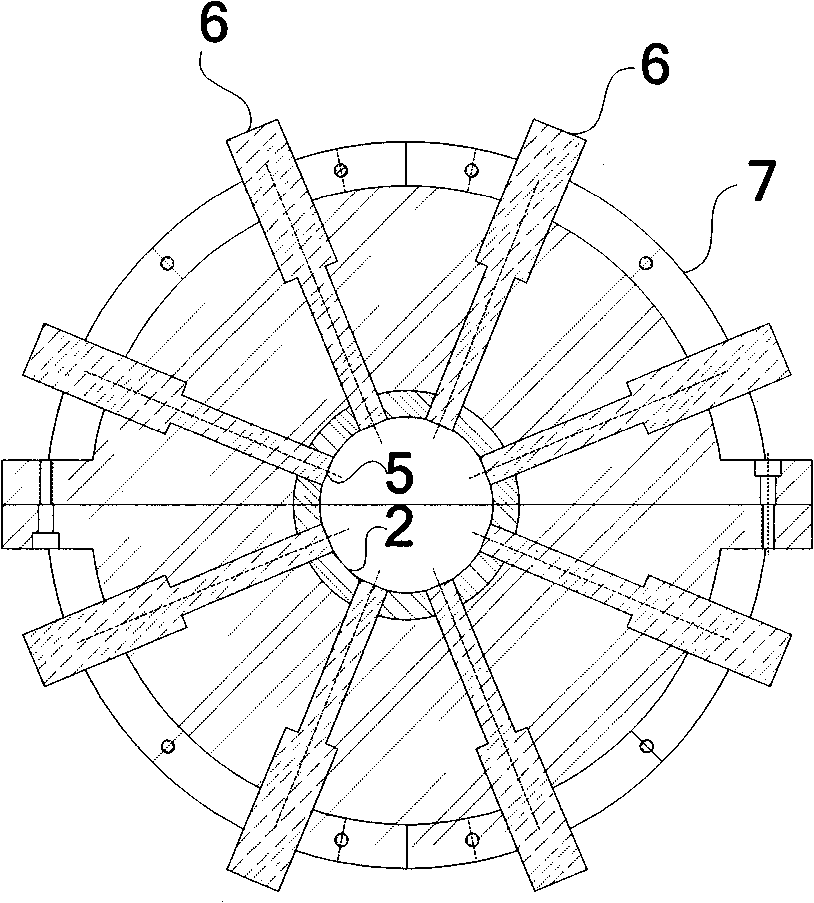
[0067] A kind of microphone calibration device of the present invention, comprises sound source 1, microphone installation section 2 to be calibrated, standard microphone installation section 3 and muffler 4,, muffler 4, microphone installation section 2 to be calibrated, standard microphone installation section 3 and sound source 1 by The flange connection is used from front to back in turn, and the internal design has a spigot for positioning, which enhances the sealing between the sound source 1, the microphone installation section 2 to be calibrated, the standard microphone installation section 3, and the muffler 4. An integral straight tube is formed inside the installation section 2 of the microphone to be calibrated, the installation section 3 of the standard microphone and the installation section of the muffler 4 .

[0068] Wherein, the sound source 1 is used ...


PUM


Abstract

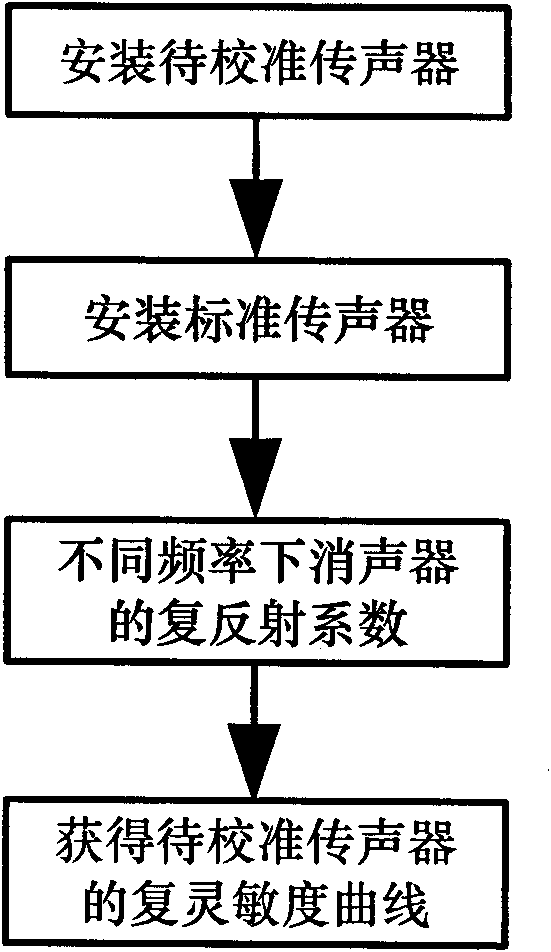
The invention discloses a microphone calibrator and a calibration method thereof. The microphone calibrator comprises a muffler, a mounting section for a microphone to be calibrated, a mounting section for a standard microphone and a sound source which are sequentially connected from front to back, wherein the mounting section for a microphone to be calibrated is provided with a mounting hole fora microphone to be calibrated, and the mounting hole is used for mounting the microphone to be calibrated; and the mounting section for a standard microphone is provided with a mounting hole for a standard microphone, and the mounting hole is used for mounting the standard microphone. The calibration method comprises the following steps: mounting two standard microphones in two mounting holes of the different standard microphones in accordance with different frequencies, measuring a complex reflection coefficient r of the muffler, and then obtaining a complex sensitivity curve of the microphone to be calibrated; and enabling the sound source to respectively send out sound waves of different frequencies, obtaining the complex sensitivity curve of the microphone to be calibrated, and thus achieving the purpose of calibrating the microphone to be calibrated. The invention can realize simultaneous calibration of a large number of microphones, thereby saving the calibration time. Besides, the invention can carry out phase calibration for a large number of microphones.

Description

technical field [0001] The invention belongs to the field of acoustic measurement, in particular to a microphone calibration device and a calibration method thereof. Background technique [0002] A microphone is a common sensor used to convert various acoustic signals into electrical signals. There are many kinds of microphones, but no matter what kind of microphone is used, it must be calibrated before use, especially when it is used as a measurement microphone. The traditional calibration method is to use a single-frequency sound source such as B&K4228 or B&K4230 for single-frequency amplitude calibration, which requires the frequency response of the microphone to have a very good linearity. Only in this way can the sensitivity of a single frequency be used as the sensitivity of the entire frequency range. Sensitivity is used. If you want to use some microphones whose frequency response curve is not flat enough, it is impossible to use this sound source for calibration. I...

Claims


Application Information

Patent Timeline
Patent Type & Authority Patents(China)
IPC IPC(8): H04R29/00
Inventor 王利王同庆
Owner BEIHANG UNIV
Learn More