Portable light source position automatic calibration system and calibration method
A light source position, automatic calibration technology, applied in key distribution, can solve the problems of poor repeatability, complex operation, large workload, etc., to achieve the effect of convenient movement and operation, simple and flexible operation, and high work efficiency
- Summary
- Abstract
- Description
- Claims
- Application Information
AI Technical Summary
Problems solved by technology
Method used
Image
Examples
Embodiment 1
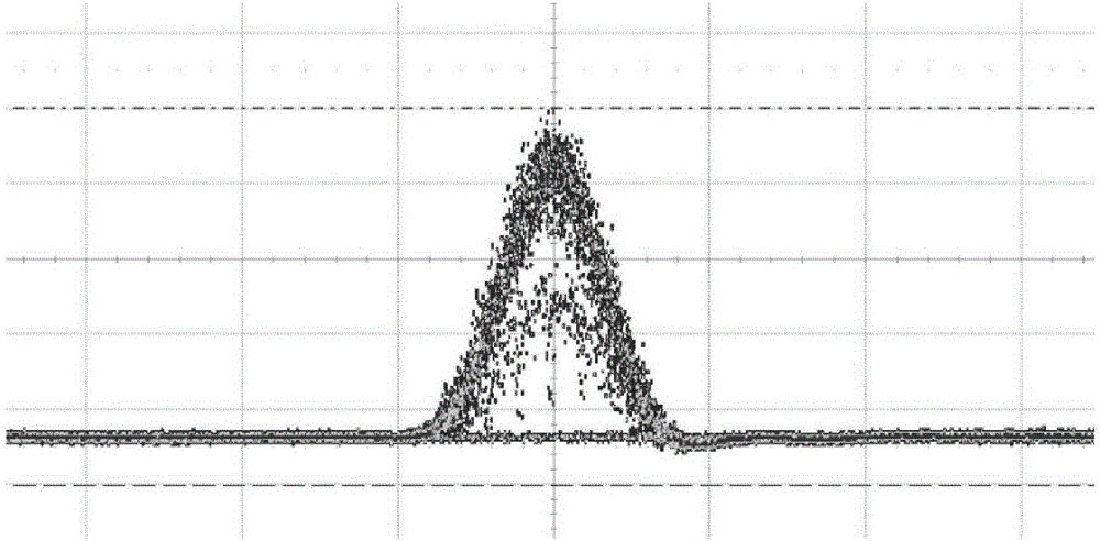
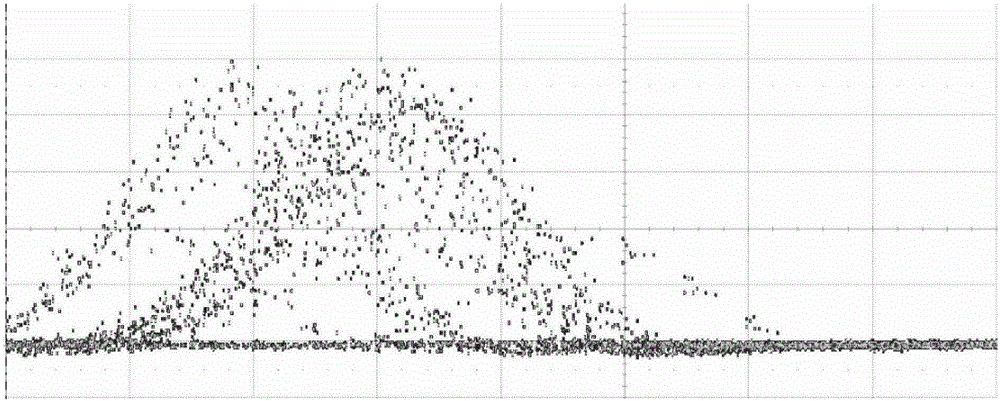
[0054] This embodiment adopts a QKD system based on polarization coding, BB84 protocol, and decoy light source. The QKD sender needs to send photons of four different polarization states, and each polarization state of photons includes two kinds of signal (signal) state and decoy (decoy) state, that is, a total of 8 kinds of light need to be sent, corresponding to 8 optical pulses, which can be Respectively denoted as h_s, v_s, p_s, n_s, h_d, v_d, p_d, n_d. Among them, the light intensity of the decoy state is weaker than that of the signal state. The QKD sender selects one of the eight light pulses at each light-emitting time according to a fixed period, so from the perspective of the time axis, all the light pulses transmitted on the optical fiber should be synthesized into one beam with a fixed Periodic optical pulse signal; if the relative positions of the optical pulses finally transmitted on the optical fiber are unstable, the positions of the eight optical pulses need ...
Embodiment 2
[0083] This embodiment adopts a QKD system based on polarization coding, B92 protocol, and non-decoy light source. The QKD sender needs to send photons of two different polarization states (H, +), corresponding to two optical pulses, and the positions of the two optical pulses need to be calibrated.
[0084] Step 1: first set the key parameters of the light source drive signal used for calibration of the QKD sender device, including frequency and code pattern. The code pattern of each light source driving signal is as follows:
[0085] The code pattern of the first channel is: 11000,
[0086] The code pattern of the second channel is: 00111;
[0087] Step 2: Perform simple logic settings on the position offset calculation module, such as start signal frequency, stop signal frequency, expected delay value, calibration accuracy, calibration times threshold and other parameters; among them, the stop signal frequency is generally set to the QKD sender The frequency of the light...
PUM
 Abstract
Description
Claims
Application Information
 - R&D
- Intellectual Property
- Life Sciences
- Materials
- Tech Scout
- Unparalleled Data Quality
- Higher Quality Content
- 60% Fewer Hallucinations
Browse by: Latest US Patents, China's latest patents, Technical Efficacy Thesaurus, Application Domain, Technology Topic, Popular Technical Reports.
© 2025 PatSnap. All rights reserved.Legal|Privacy policy|Modern Slavery Act Transparency Statement|Sitemap|About US| Contact US: help@patsnap.com


