Supercharge Your Innovation With Domain-Expert AI Agents!

Downhole load sharing motor assembly

A load sharing, motor technology, applied in wellbore/well components, electrical components, drilling equipment, etc., can solve problems such as impracticality

Inactive Publication Date: 2010-11-24
PRAD RES & DEV LTD
View PDF0 Cites 0 Cited by
  • Summary
  • Abstract
  • Description
  • Claims
  • Application Information

AI Technical Summary

Problems solved by technology

This makes using conventional mechanical motors generally impractical

Method used


Image

  • Downhole load sharing motor assembly
  • Downhole load sharing motor assembly
  • Downhole load sharing motor assembly

Examples


Embodiment Construction

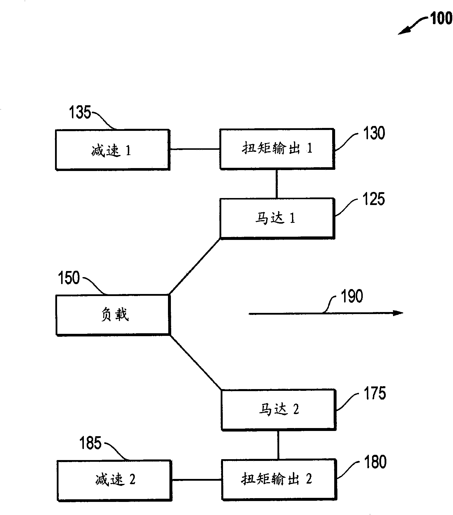
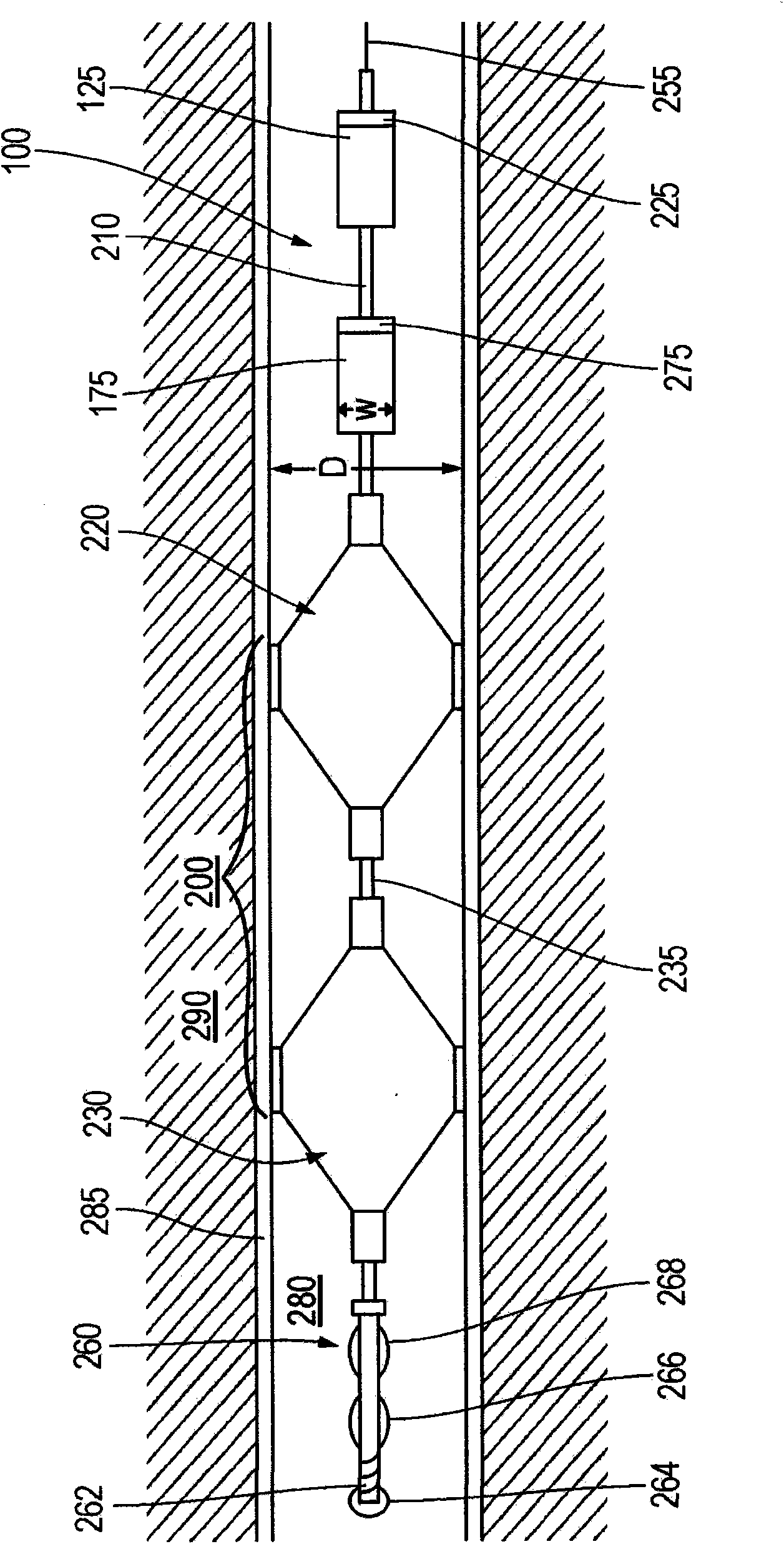
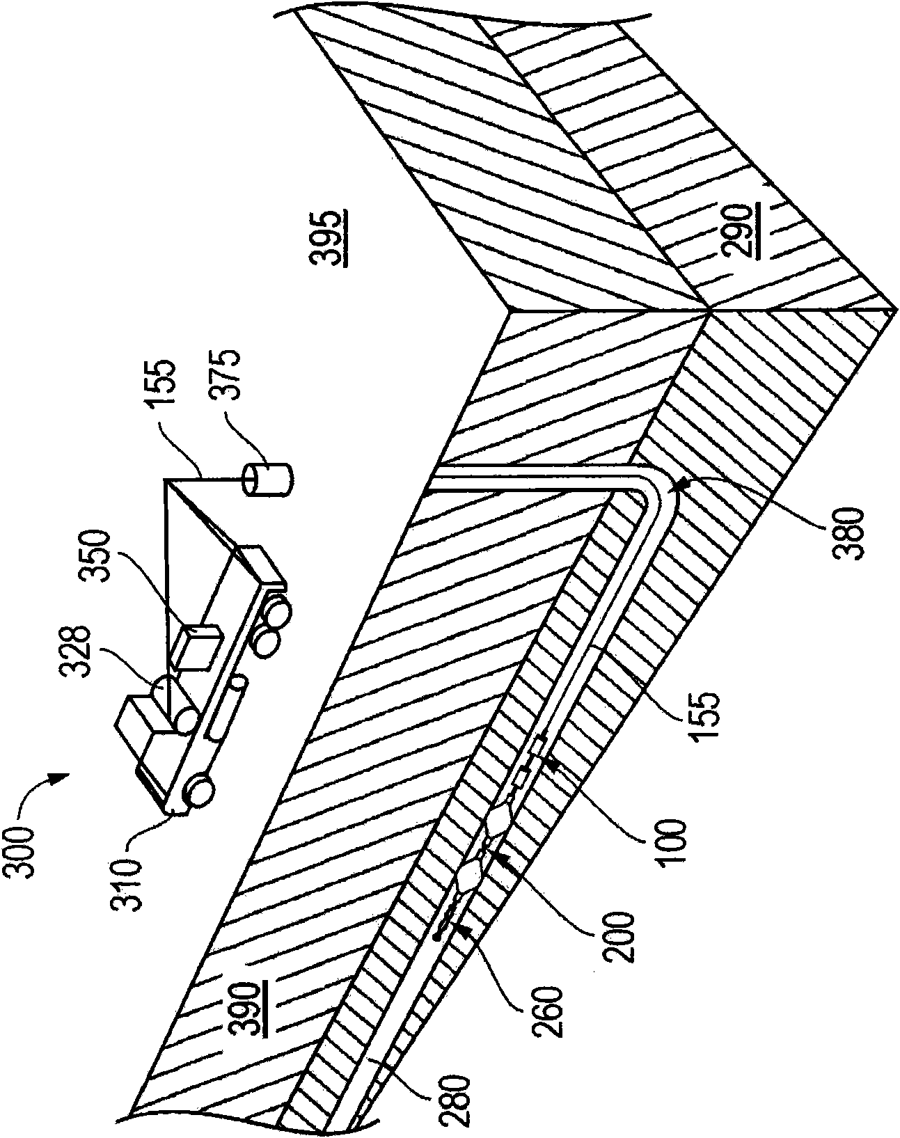
[0018] Embodiments are now described with reference to a particular downhole multi-motor assembly configured to share a load. Specifically, an assembly employing two permanent magnet synchronous machine (PMSM) motors will be described. However, other types of motor assemblies with different numbers of motors may also be used. For example, more than two motors may be used for the assembly. Regardless, embodiments described herein include assemblies with downhole PMSM motors, or other substantially constant speed adjustable speed motors configured to exhibit a generally balanced torque output during downhole operations. Furthermore, as used herein, the term "substantially constant speed adjustable speed motor" refers to a motor configured to operate at a substantially constant speed during operation, such as a conventional PMSM, but the term also actively directs the adjustment of speed during operation. its speed.

[0019] now refer to figure 1 , depicts a schematic diagram...


PUM


Abstract

A motor assembly of multiple motors for use in driving a shared downhole load within a well. In particular, the assembly may employ substantially constant adjustable speed motors. These may include permanent magnet synchronous machine motors. The motors may be configured to operate at given speeds that may be downwardly adjusted depending on the amount of torque output independently exhibited by the individual motors. In this manner, a significant divergence in torque output between the motors may be avoided so as to ensure substantial load sharing between all of the motors of the assembly.

Description

technical field [0001] Embodiments described herein relate to motors used to drive loads downhole in a wellbore. In particular, an embodiment of a load sharing motor in the form of a downhole power assembly is described. The motor assembly may be configured to be sized for the downhole environment and drive a load with improved load sharing between the motors themselves. Background technique [0002] Drilling, completing, and operating hydrocarbon wellbores involves the use of a variety of power equipment. Examples of large-scale surface equipment typically used in oil fields are positive displacement pumps, mixers, and material transport units, among others. In addition, a lot of small downhole equipment, such as tractors and logging equipment, is often used in the wellbore itself. As detailed below, a piece of surface equipment, such as a single positive displacement pump, may be powered by multiple motors that share the load driving the operation of the pump. In fact,...

Claims


Application Information

Patent Timeline
Patent Type & Authority Applications(China)
IPC IPC(8): E21B4/04
CPCE21B4/04E21B4/16E21B43/128H02P5/46E21B4/18H02P5/00
Inventor 迈克尔·蒙托伊斯托多尔·希雷托夫
Owner PRAD RES & DEV LTD
Features
  • R&D
  • Intellectual Property
  • Life Sciences
  • Materials
  • Tech Scout
  • Unparalleled Data Quality
  • Higher Quality Content
  • 60% Fewer Hallucinations
Learn More