Methods and apparatuses for fault management in permanent magnet synchronous machines using the field reconstruction method

a permanent magnet synchronous machine and field reconstruction technology, applied in the direction of electronic commutators, motor/generator/converter stoppers, dynamo-electric converter control, etc., can solve the problem of increasing the computational cost of the whole system, the amount of time required to carry out the task, and the inability of fea methods to meet real-time control schemes

Inactive Publication Date: 2012-11-20
BOARD OF RGT THE UNIV OF TEXAS SYST
View PDF5 Cites 20 Cited by
  • Summary
  • Abstract
  • Description
  • Claims
  • Application Information

AI Technical Summary

Problems solved by technology

Although accurate, the main problem with FEA based methods is the amount of time which is necessary to carry out the task.
Therefore FEA methods are inappropriate for real time control schemes.
Also, FEA methods increase the computational expense of the whole system.
In addition, there are issues in flux estimation using conventional methods as they use voltage integration which leads in significant numerical errors in low speed applications.

Method used


Image

  • Methods and apparatuses for fault management in permanent magnet synchronous machines using the field reconstruction method
  • Methods and apparatuses for fault management in permanent magnet synchronous machines using the field reconstruction method
  • Methods and apparatuses for fault management in permanent magnet synchronous machines using the field reconstruction method

Examples


Embodiment Construction

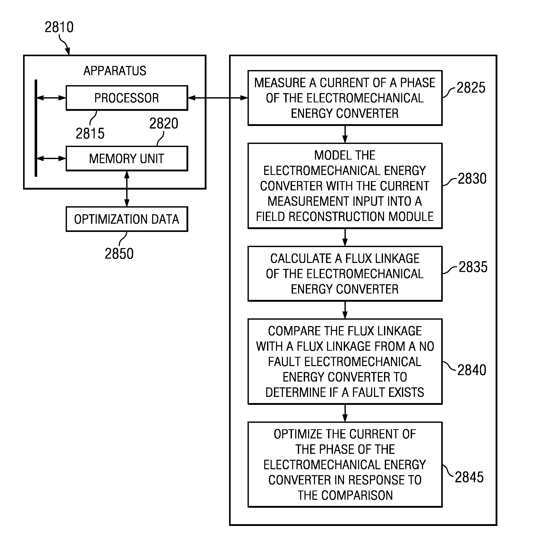
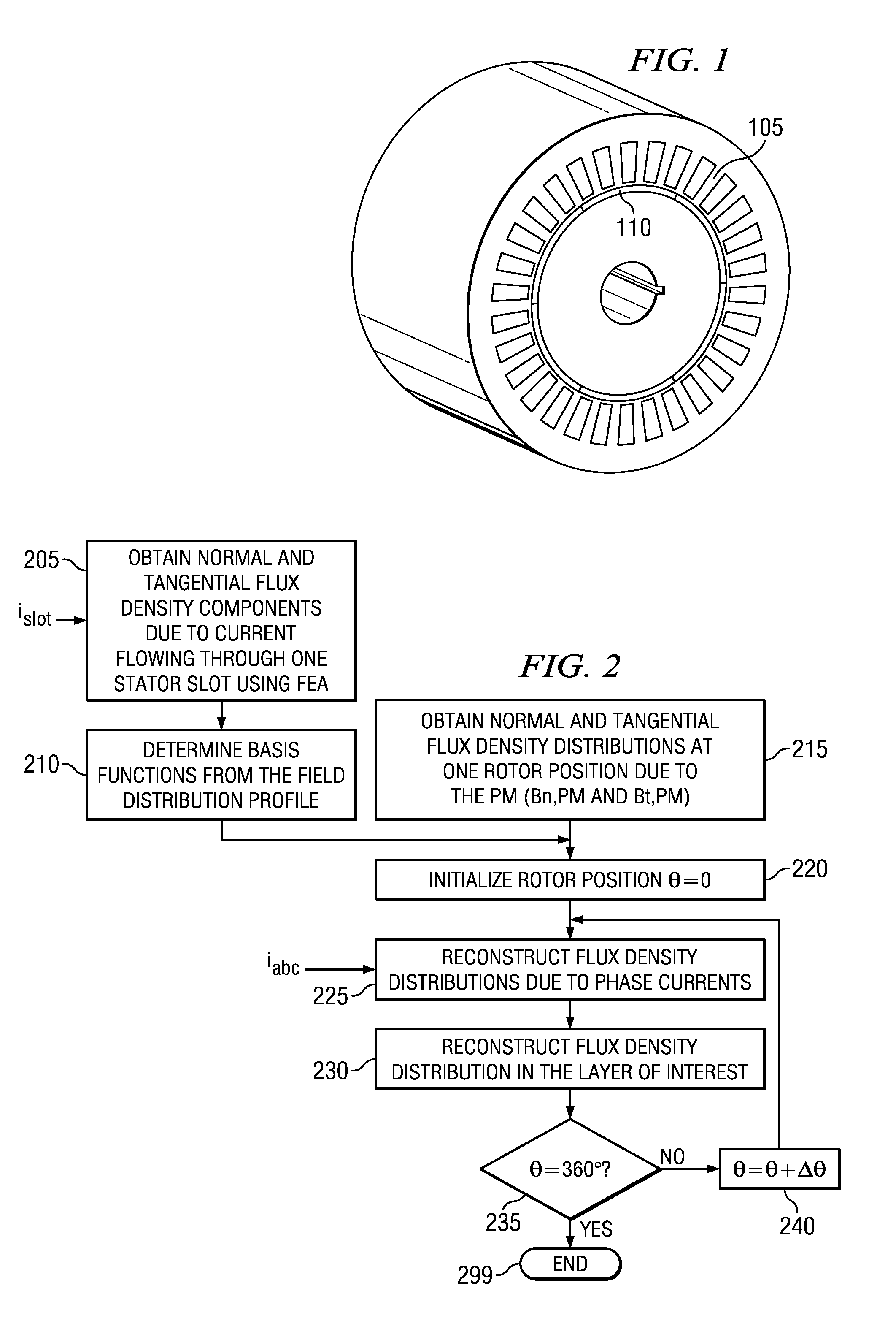
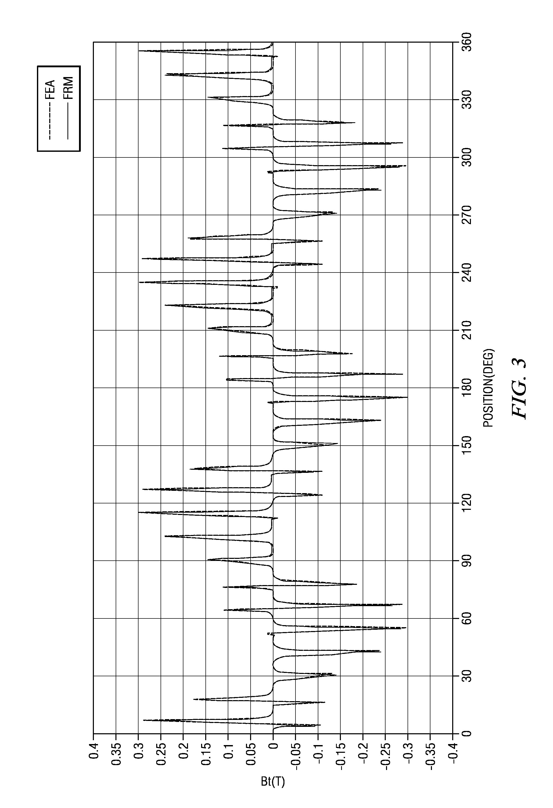
[0040]The drawing figures are not necessarily to scale and certain features may be shown exaggerated in scale or in somewhat generalized or schematic form in the interest of clarity and conciseness. In the description which follows like parts may be marked throughout the specification and drawing with the same reference numerals. The foregoing description of the figures is provided for a more complete understanding of the drawings. It should be understood, however, that the embodiments are not limited to the precise arrangements and configurations shown. Although the design and use of various embodiments are discussed in detail below, it should be appreciated that the present invention provides many inventive concepts that may be embodied in a wide variety of contexts. The specific aspects and embodiments discussed herein are merely illustrative of ways to make and use the invention, and do not limit the scope of the invention. It would be impossible or impractical to include all of...


PUM


Abstract

Methods and apparatuses for detecting faults and optimizing phase currents in an electromechanical energy converter are disclosed. An example method comprises: measuring a current of a phase of the electromechanical energy converter, modeling the electromechanical energy converter with the current measurement input into a field reconstruction module, calculating a flux linkage of the electromechanical energy converter, comparing the flux linkage with a flux linkage from a no fault electromechanical energy converter, and optimizing the current of the phase of the electromechanical energy converter in response to the comparison. Other embodiments are described and claimed.

Description

CROSS REFERENCE TO RELATED APPLICATIONS[0001]This application claims the benefit of the filing date of U.S. provisional patent application No. 61 / 226,667, incorporated herein by reference, which was filed on Jul. 17, 2009, by the same inventors of this application.STATEMENT REGARDING FEDERALLY SPONSORED RESEARCH[0002]This invention was made with government support under Contract Number N00014-09-1-0572 awarded by the Office of Naval Research. The government has certain rights in the invention.FIELD OF THE INVENTION[0003]The present invention generally relates to fault management in multi-phase permanent magnet synchronous machines. More particularly, the invention relates to fault detection and post fault treatment using the field reconstruction method.BACKGROUND OF THE INVENTION[0004]The embodiment described herein relates generally to the field of fault detection in permanent magnet synchronous machines (PMSM) and the subsequent management of the faults after detection. The field ...

Claims


Application Information

Patent Timeline
Patent Type & Authority Patents(United States)
IPC IPC(8): H02P6/12H02P23/14
CPCH02P23/14H02P21/141H02P23/12H02P2207/05
Inventor FAHIMI, BABAKKHOOBROO, AMIR
Owner BOARD OF RGT THE UNIV OF TEXAS SYST
Why Eureka
Try Eureka