Device for control of a pmsm

a technology of a pmsm and a control device, which is applied in the direction of electronic commutators, motor/generator/converter stoppers, dynamo-electric converter control, etc., can solve the problems of fast current response and torque, and achieve the effect of simple production and longer li

Active Publication Date: 2012-11-08
SAFRAN ELECTRICAL & POWER
View PDF14 Cites 17 Cited by
  • Summary
  • Abstract
  • Description
  • Claims
  • Application Information

AI Technical Summary

Benefits of technology

[0025]A sensorless control device is particularly robust, since it has one fewer detection elements. A sensorless control device is thus simpler to produce, and can have a longer lifetime than a control device with sensors.

Problems solved by technology

In addition, it has relatively low inductances, which leads to fast responses of the currents and therefore of the torque.

Method used


Image

  • Device for control of a pmsm
  • Device for control of a pmsm
  • Device for control of a pmsm

Examples


Embodiment Construction

[0064]Other characteristics and advantages of the invention will appear on reading the preferential embodiments of the invention made in reference to the attached figures, among which:

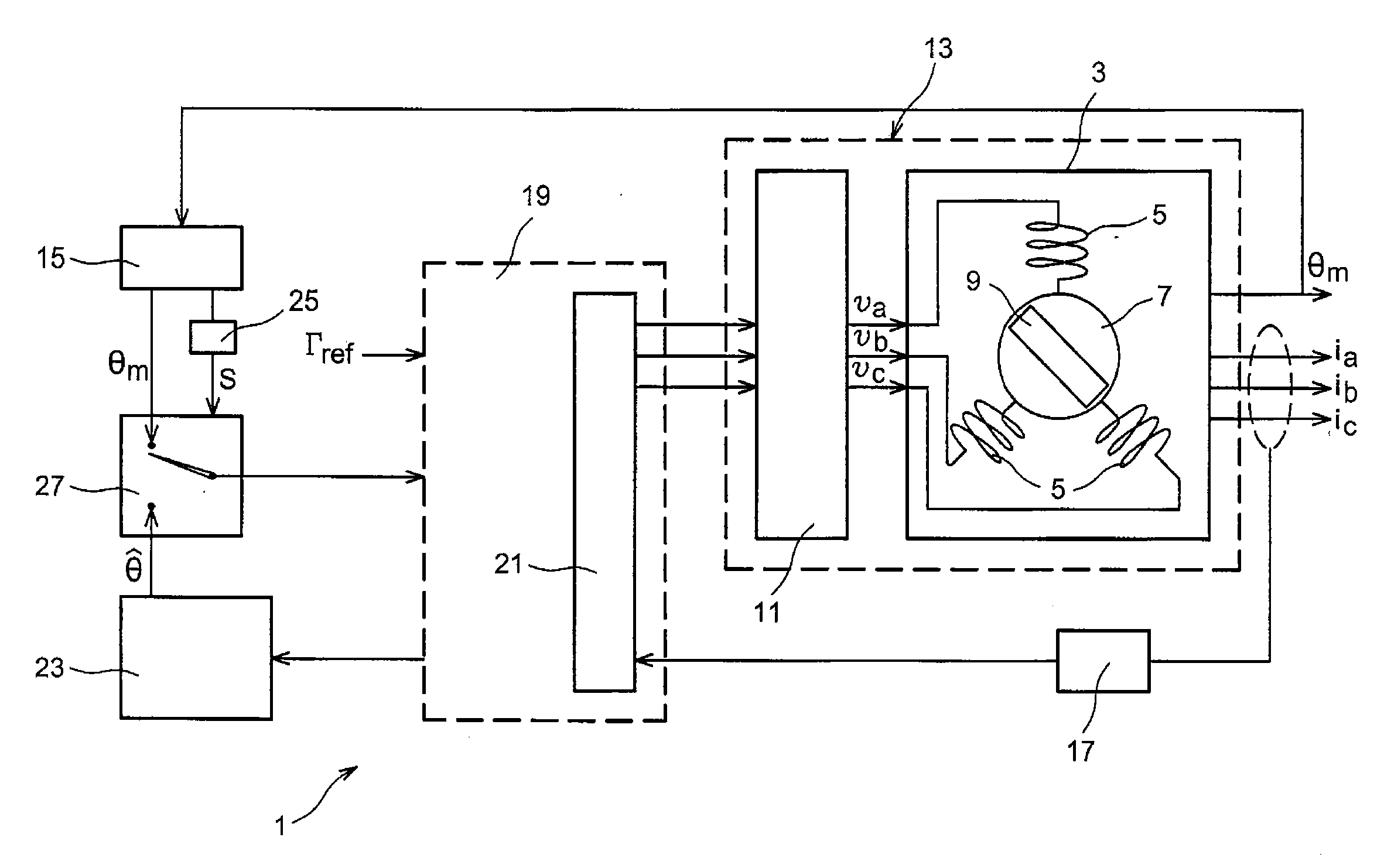
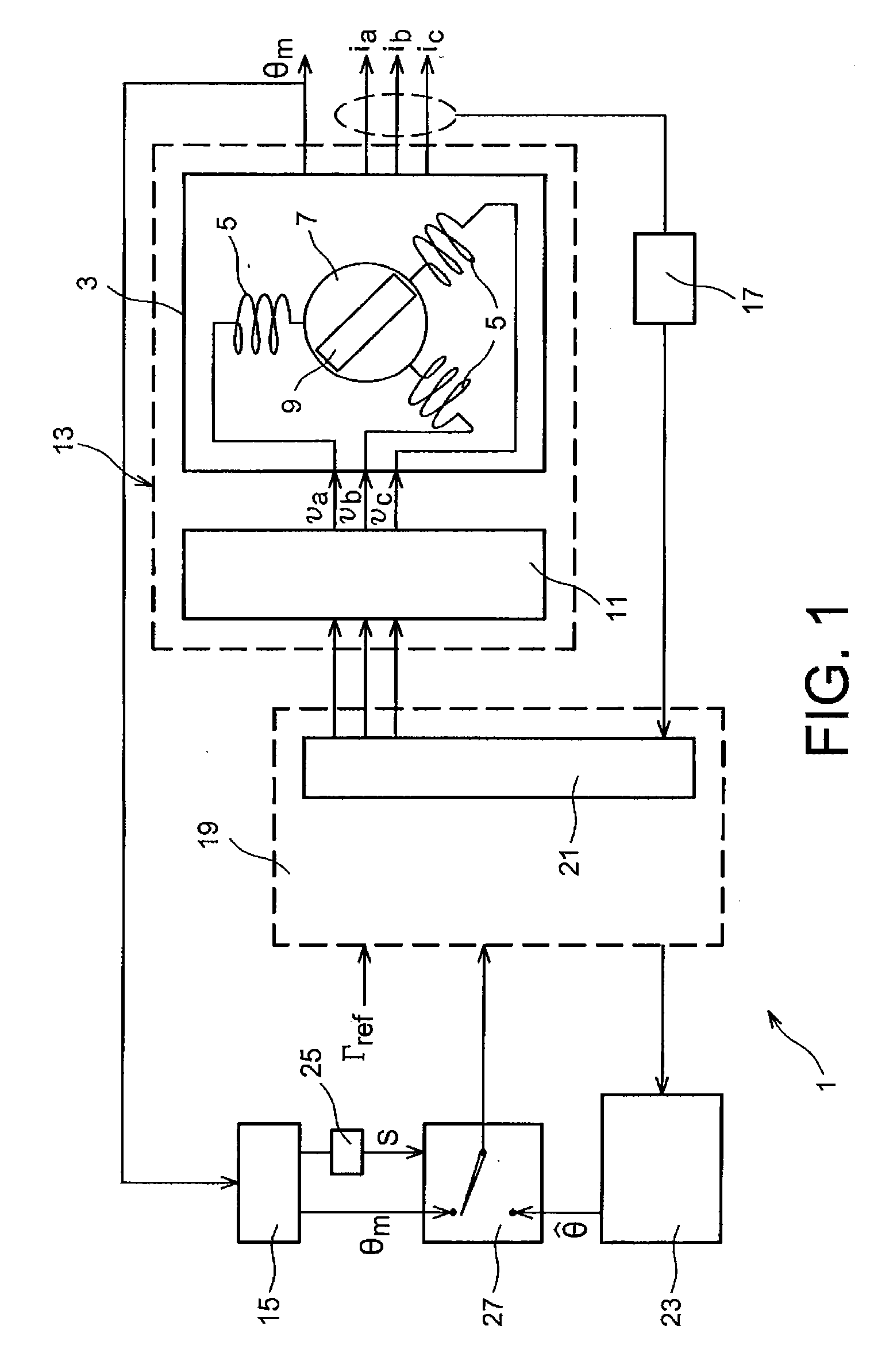
[0065]FIG. 1 represents diagrammatically a permanent magnet synchronous machine “PMSM”, according to the invention;

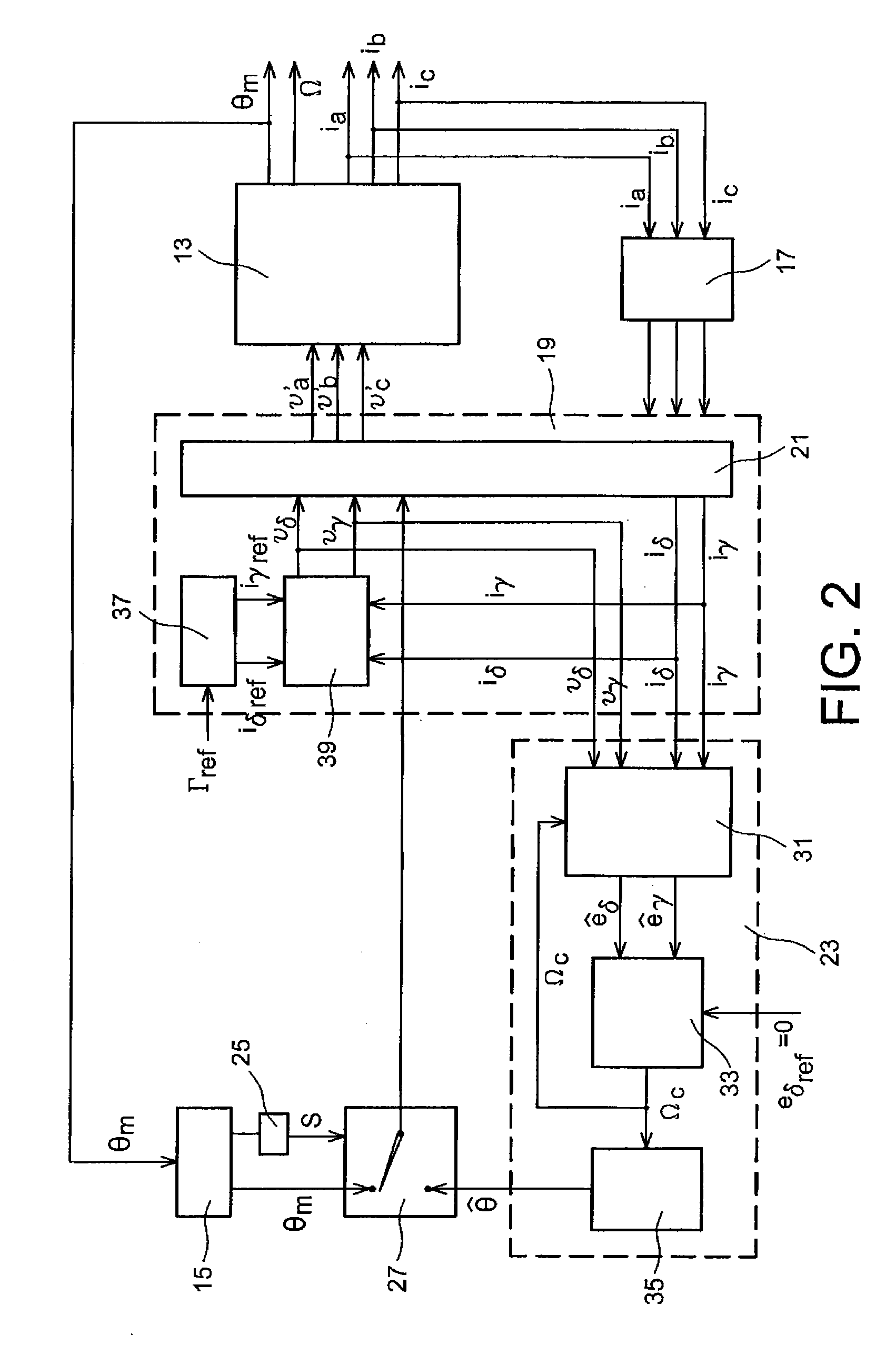
[0066]FIG. 2 represents diagrammatically an embodiment of the control device of FIG. 1;

[0067]FIG. 3 represents diagrammatically an embodiment of the speed estimator illustrated in FIG. 2;

[0068]FIGS. 4A and 4B represent diagrammatically particular embodiments of the adjustment means illustrated in FIGS. 1 and 2;

[0069]FIG. 5 represents diagrammatically a device to control a PMSM, according to the prior art,

[0070]FIG. 6 represents a Park frame of reference associated with the rotor of a PMSM; and

[0071]FIG. 7 represents diagrammatically a device to control a sensorless PMSM, according to the prior art.

DETAILED ACCOUNT OF PARTICULAR EMBODIMENTS

[0072]FIG. 1 represents diagrammatically a device 1...


PUM


Abstract

A permanent magnet synchronous machine (PMSM) includes a stator and rotor powered by an inverter. A device to control the PMSM includes a sensor to sample a measurement θm of the position of the rotor, a control unit to control an operating point of the PMSM according to the position of the rotor and settings, and an estimation unit to determine an estimate {circumflex over (θ)} of the rotor position. The device also includes a malfunction detector to detect a malfunction of the sensor and a switch to connect the control unit to the sensor so that the control unit receives the measured position θm of the rotor while the malfunction detector does not indicate any sensor malfunction, and otherwise to connect the control unit to the estimation unit so that the control unit receives the estimated position {circumflex over (θ)} of the rotor when the malfunction detector indicates a sensor malfunction.

Description

TECHNICAL FIELD[0001]The present invention concerns the field of control of permanent magnet synchronous machines (PMSM).STATE OF THE PRIOR ART[0002]A permanent magnet synchronous machine (PMSM) includes a stator and a rotor. Generally, the stator includes windings connected in a star shape and the rotor includes permanent magnets.[0003]A PMSM is habitually powered by an inverter which enables the currents' ripple factor and torque of the machine to be reduced.[0004]A PMSM has a high torque and very low inertia. In addition, it has relatively low inductances, which leads to fast responses of the currents and therefore of the torque.[0005]It is therefore very advantageous to use PMSMs in the motor of high-power and high-performance actuators, notably in on-board aircraft systems.[0006]FIG. 5 represents diagrammatically a system including a control device 101, an inverter 111 and a PMSM 103.[0007]Inverter 111 powers PMSM 103 using direct voltage. It enables amplitude and frequency vol...

Claims


Application Information

Patent Timeline
Patent Type & Authority Applications(United States)
IPC IPC(8): H02P6/16
CPCH02P21/13H02P21/14H02P23/14H02P21/146H02P21/145H02P21/16H02P21/18
Inventor LEJEUNE, GUILHEMVIEILLARD, SEBASTIEN
Owner SAFRAN ELECTRICAL & POWER
Why Eureka
Try Eureka