Check patentability & draft patents in minutes with Patsnap Eureka AI!

Paper cutting mechanism

A paper cutting and cutting technology, applied in metal processing and other directions, can solve problems such as increasing costs, and achieve the effect of reducing costs and simplifying complexity

Inactive Publication Date: 2012-05-30
PRIMAX ELECTRONICS LTD
View PDF0 Cites 0 Cited by
  • Summary
  • Abstract
  • Description
  • Claims
  • Application Information

AI Technical Summary

Problems solved by technology

Also, the design using two lead screws adds cost

Method used


Image

  • Paper cutting mechanism
  • Paper cutting mechanism
  • Paper cutting mechanism

Examples


Embodiment Construction

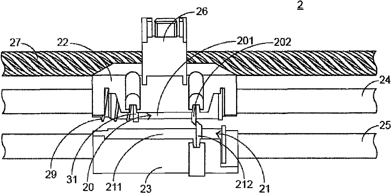
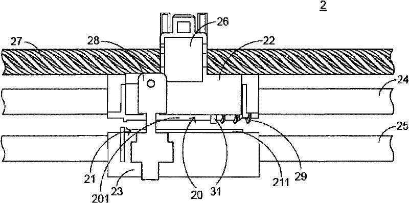
[0033] See figure 2 and image 3 , figure 2 It is a front view of the appearance structure of the preferred embodiment of the paper cutting mechanism of the present invention, image 3 It is a rear view of the appearance structure of the preferred embodiment of the paper cutting mechanism of the present invention. The paper cutting mechanism 2 of the present invention includes first and second cutter sets 20, 21, first and second cutter sets 22, 23, first and second guide shafts 24, 25, lead screw sleeve 26, and lead screw 27. The connecting device 28 and a spring 29. In addition, the first tool group 20 includes a first tool holder 201 and a first tool 202, and the second tool group 21 includes a second tool holder 211 and a second tool 212.

[0034] Wherein, the first guide shaft 24 passes through the first tool set 20, and the second guide shaft 25 passes through the second tool set 21, and the first and second tool sets 22 and 23 are respectively used to hold the first tool...


PUM


Abstract

The invention relates to a paper cutting mechanism. The paper cutting mechanism comprises a first cutter group, a second cutter group, a first cutter group sleeve, a second cutter group sleeve, a first guiding shaft, a second guiding shaft, a guide screw, a guide screw shaft sleeve and a connecting device. The paper cutting mechanism synchronously drives the first cutter group and the second cutter group by the guide screw only so as to realize the function of cutting paper. The paper cutting mechanism has the advantages of reducing cost and simplifying the complexity of synchronous control of the first cutter group and the second cutter group.

Description

Technical field [0001] The invention relates to a cutting mechanism, in particular to a cutting mechanism using a single lead screw. Background technique [0002] Nowadays, the paper cutting mechanism with the function of cutting paper, whether it is for the increase of functions or economic considerations, based on the increasingly diversified needs of users, its product categories are constantly innovating. [0003] One example is the receipt cutting mechanism using a lead screw. See figure 1 , Which is a schematic diagram of the existing receipt paper cutting mechanism. The main method is to insert a piece of paper into the paper cutting mechanism 1 in the direction I, so that the paper is cut to the width of the invoice. [0004] The paper cutting mechanism 1 includes first and second cutter sets 10, 11, first and second cutter sets 12, 13, first and second guide shafts 14, 15, and first and second lead screw sleeves 16 , 17, and the first and second lead screws 18, 19. In ad...

Claims


Application Information

Patent Timeline
Patent Type & Authority Patents(China)
IPC IPC(8): B26D1/03
Inventor 管建国
Owner PRIMAX ELECTRONICS LTD
Features
  • R&D
  • Intellectual Property
  • Life Sciences
  • Materials
  • Tech Scout
  • Unparalleled Data Quality
  • Higher Quality Content
  • 60% Fewer Hallucinations
Learn More